
Eclipse L4-1997cc 2.0L DOHC (1991)
Continuity: ............................................................................................................................................................................................ Should exist
4. Remove power from terminal 6.
5. Check for continuity between terminals 7 and 3.
Continuity: ........................................................................................................................................................................................ Should not exist
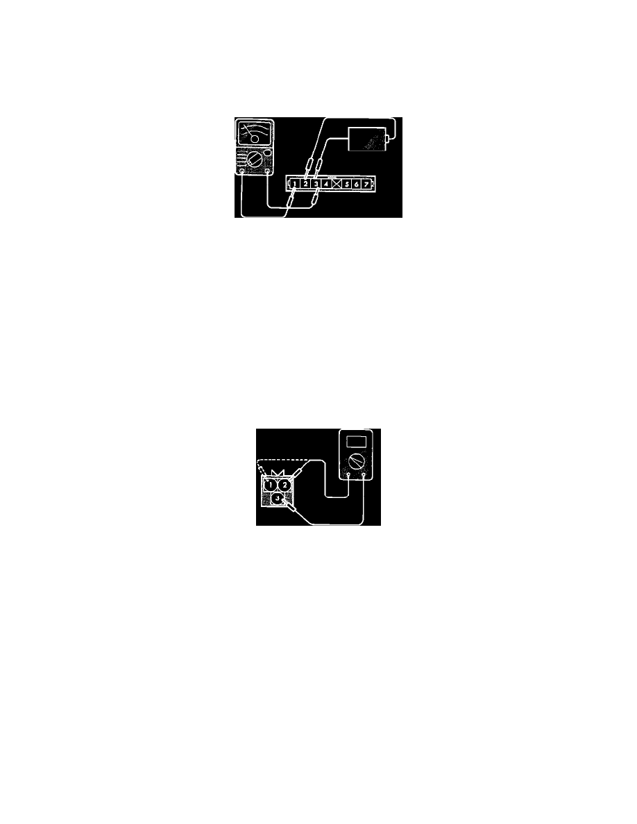
Power Transistor (Ignition Coil 3 & 4) Test
NO. 2 & NO. 3 COIL SIDE
1. Disconnect the power transistor connector.
2. Connect a power supply of 1.5v (one dry cell) between power transistor terminals 2 (+) and 3 (-).
3. Check for continuity between terminals 3 and 1.
Note: Connect the negative probe of the tester to terminal 1 of the power transistor.
Continuity: .............................................................................................................................................................................................. Should exist
4. Remove power from terminal 2.
5. Check for continuity between terminals 3 and 1.
Continuity: ...................................................................................................................................................................................... Should not exist
If the Power Transistor fails any of these tests, replace the Power Transistor.
Ignition Coil Test
IGNITION COIL
1. Disconnect the ignition coil connector.
2. Using an ohm meter, check the resistance between terminals 2 and 3. (The coils at 1 and 4 cyls)
Resistance: ..................................................................................................................................................................................... 0.77 - 0.95 Ohms
3. Using an ohm meter, check the resistance between terminals 1 and 3. (The coils at 2 and 3 cyls)
Resistance: ..................................................................................................................................................................................... 0.77 - 0.95 Ohms