
Eclipse L4-1997cc 2.0L DOHC Turbo 16 Valve (1996)
identification colors of its pins are painted at the positions shown.
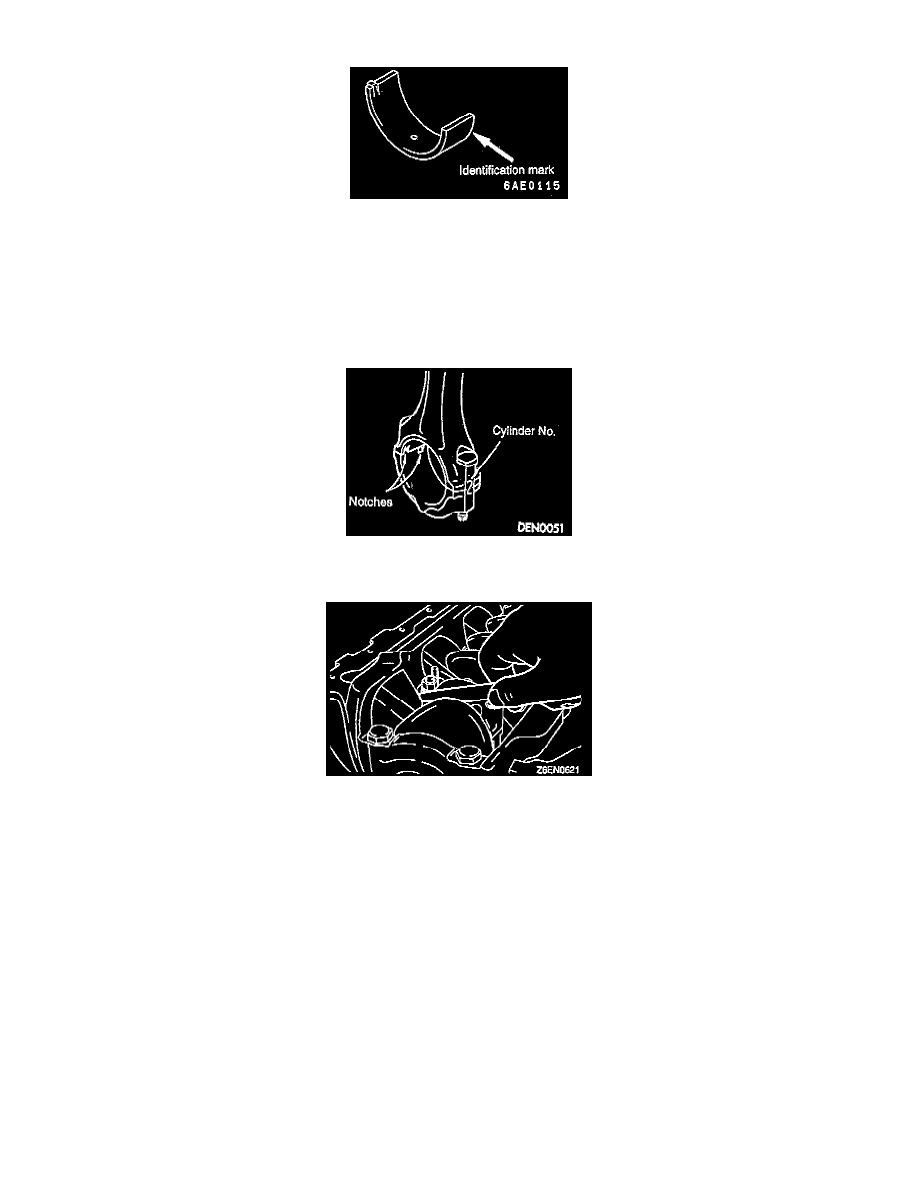
24. The connecting rod bearing identification mark is stamped at the position shown in the illustration. Connecting rod I.D. is 48.000 - 48.015 mm
(1.8900 - 1.8904 inch).
25. Select a proper bearing from the table on the basis of the identification data confirmed under steps 23 and 24.
Example: If the measured value of a crankshaft pin outer diameter is between 44.995 and 45.000 mm (1.7715 and 1.7717 inch), the pin is
classified as "1" in the table. In case the crankshaft is also replaced by a spare part, check the identification colors of the pins painted on the new
crankshaft. If the color is yellow, for example, the pin is classified as "1". In the above cases, select the connecting rod bearing having
identification mark "1".
26. Verifying the mark made during disassembly, install the bearing cap to the connecting rod. If the connecting rod is new with no index mark, make
sure that the bearing locking notches come on the same side as shown.
27. Make sure that the connecting rod big end side clearance meets the specification. The standard value is 0.10 - 0.25 mm (0.0039 - 0.0098 inch) and
the limit is 0.4 mm (0.016 inch).
NOTE: Installation of the connecting rod nut should be performed with the cylinder head or the spark plug removed.
28. Since the connecting rod bolts and nuts are torqued using the plastic area tightening method, the bolts should be examined before reuse. If the bolt
threads are "necked down", the bolt should be replaced.
NOTE: Necking can be checked by running a nut with fingers to the full length of the bolt threads. If the nut does not run down smoothly, the bolt
should be replaced.
29. Before installation of each nut, apply engine oil to the threaded portion and bearing surface of the nut.
30. Loosely tighten each nut to the bolt.
31. Then tighten the nuts alternately to a torque of 20 Nm (14.5 ft. lbs.) to install the cap properly.
32. Make a paint mark on the head of each nut.
33. Make a paint mark on the bolt end at the position 90° - 100° from the paint mark made on the nut in the direction of tightening the nut.
34. Give a 90° - 100° turn to the nut and make sure that the paint mark on the nut and that on the bolt are in alignment.
NOTE:
-
If the nut is turned less than 90°, proper fastening performance may not be expected. When tightening the nut, therefore, be careful to give a
sufficient turn to it.