
Eclipse L4-1997cc 2.0L DOHC Turbo 16 Valve (1996)
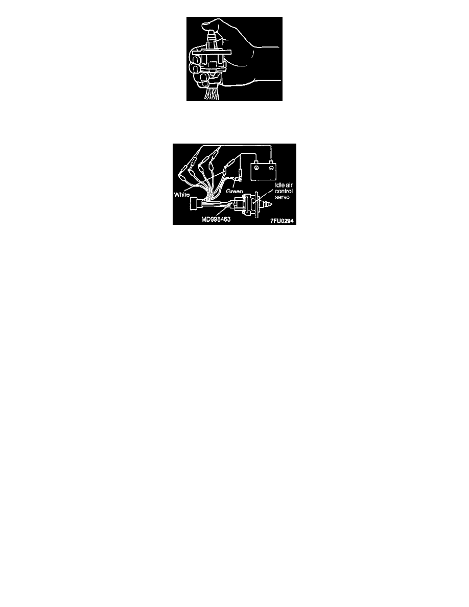
5. With the idle air control motor as shown in the illustration, connect the negative (-) terminal of the power supply to each clip as described in the
following steps, and check whether or not a vibrating feeling (a feeling of very slight vibration of the stepper motor) is generated as a result of the
activation of the stepper motor.
(1) Connect the negative (-) terminal of the power supply to the red and black clip.
(2) Connect the negative (-) terminal of the power supply to the blue and black clip.
(3) Connect the negative (-) terminal of the power supply to the blue and yellow clip.
(4) Connect the negative (-) terminal of the power supply to the red and yellow clip.
(5) Connect the negative (-) terminal of the power supply to the red and black clip.
(6) Repeat the tests in sequence from (5) to (1).
6. If, as a result of these tests, vibration is detected, the stepper motor can be considered to be normal.