
Eclipse L4-2.4L SOHC (2004)
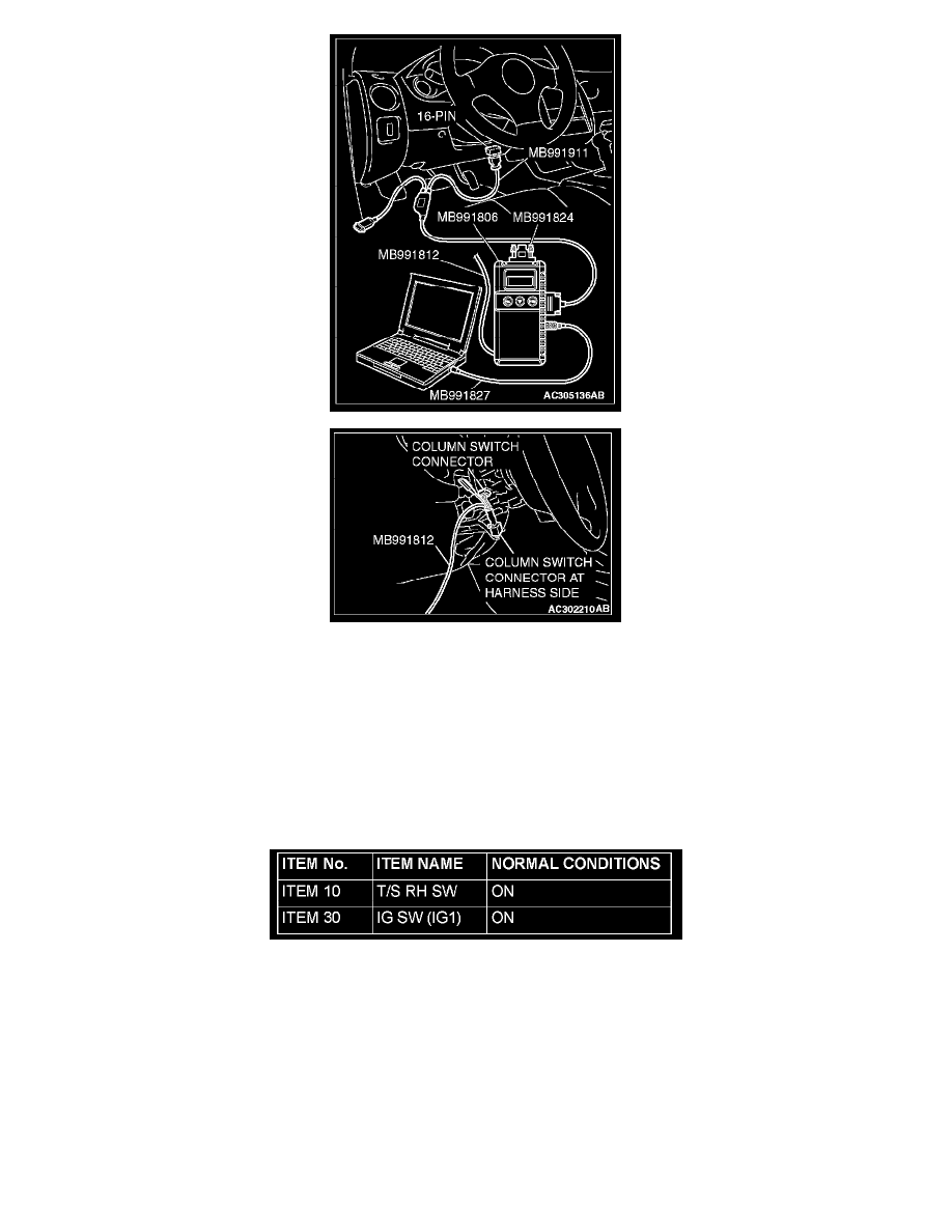
1. Connect the special tool. Refer to "How to connect SWS monitor." See: Reading and Clearing Diagnostic Trouble Codes/How to Connect SWS
Monitor
2. Turn the ignition switch to the "LOCK" (OFF) position.
3. Operate scan tool MB991958 according to the procedure below to display "TURN SIG.RH."
a. Select "Interactive Diagnosis."
b. Select "System select."
c. Select "SWS."
d. Select "SWS MONITOR."
e. Select "Function Diag."
f.
Select "TURN SIGNAL."
g. Select "TURN SIG.RH."
4. Check that normal conditions are displayed on the items described in the given table.
Q: Does the scan tool display the items "T/S RH SW" and "IG SW (IG1)" as normal condition?
Normal conditions are displayed for all the items: Go to Step 8.
The scan tool does not show the respective normal condition for item "T/S RH SW": Refer to Inspection Procedure O-7 "ETACS-ECU does
not receive any signal from the taillight switch, the headlight switch, the passing light switch, the dimmer switch, the turn-signal light switch or
switch."
The scan tool does not show the respective normal condition for item "IG SW (IG1)": Refer to Inspection Procedure O-2 "ETACS-ECU does
not receive a signal from the ignition switch (IG1)."