
Eclipse L4-2.4L SOHC (2004)
DIAGNOSIS
Required Special Tools:
-
MB991223: Harness Set
-
MB991958: Scan Tool (MUT-III Sub Assembly)
-
MB991824: Vehicles communication interface
-
MB991827: MUT-III USB cable
-
MB991911: MUT-III Main harness B
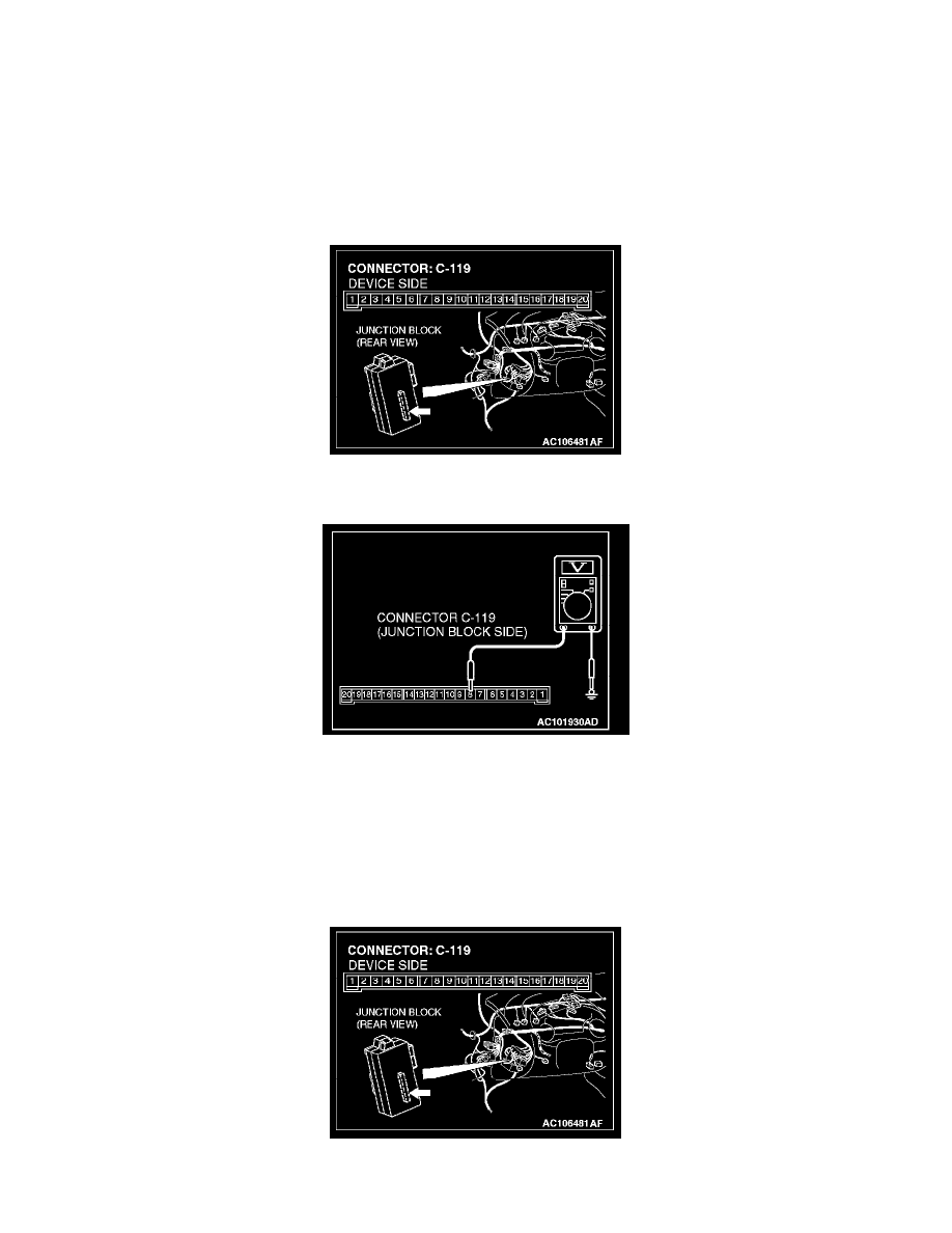
STEP 1. Measure at ETACS-ECU connector C-119 in order to check the line from the ignition switch (IG1) to the ETACS-ECU.
1. Disconnect ETACS-ECU connector C-119, and measure at the junction block side.
2. Turn the ignition switch to the "ON" position.
3. Measure the voltage between terminal 8 and ground.
-
The measured value should be approximately 12 volts (battery positive voltage).
Q: Does the measured voltage correspond with this range?
YES: Replace the ETACS-ECU. If the functions, which are described in "CIRCUIT OPERATION", work normally, the input signal from the
ignition switch (IG1) should be normal.
NO: Go to Step 2.
STEP 2. Check ETACS-ECU connector C-119 for damage.