
Eclipse L4-2.4L SOHC (2004)
]]A[[ PRE-INSTALLATION INSPECTION
WARNING: Dispose of air bag modules only according to the specified procedure.
1. When installing the new air bag modules and clock spring, Refer to "INSPECTION."
2. Connect the negative (-) battery cable.
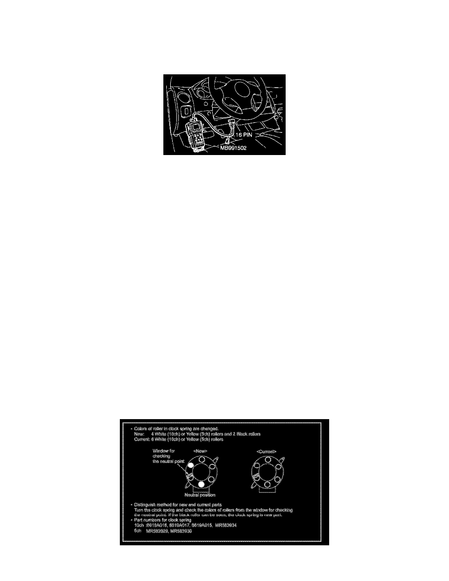
CAUTION: To prevent damage to scan tool MB991502, always turn the ignition switch to the "LOCK" (OFF) position before connecting or
disconnecting scan tool MB991502.
3. Connect scan tool MB991502 to the data link connector.
4. Turn the ignition switch to the "ON" position.
5. Conduct diagnostic test using scan tool MB991502 to ensure entire SRS operates properly.
DANGER: Wait at least 60 seconds after disconnecting the battery cable before doing any further work.
WARNING: Battery posts, terminals and related accessories contain lead and lead compounds. WASH HANDS AFTER HANDLING.
6. Turn the ignition switch to the "LOCK" (OFF) position. Disconnect the negative (-) battery cable and tape the terminal to prevent accidental
connection and air bags deployment.
]]B[[ CLOCK SPRING INSTALLATION
WARNING: Ensure that the clock spring's mating marks are properly aligned. If not, the steering wheel may not rotate completely during a
turn, or the flat cable in the clock spring could be damaged. This would prevent normal SRS operation and possibly cause serious injury to the
driver.
Align the mating marks of the clock spring. Turn the front wheels to the straight-ahead position. Then install the clock spring to the column switch.
The content of this article reflects the changes identified in TSB-08-52B-001
A modified clock spring has been adopted for Service Parts on affected vehicles as of September 2007. New and old style parts are interchangeable. This
TSB advises the procedures for alignment of the neutral point of the new clock spring when a part is replaced.
Parts Identification
Replacement Clockspring Alignment As Per Manual Update TSB-08-52B-001