
Eclipse V6-3.0L SOHC (2003)
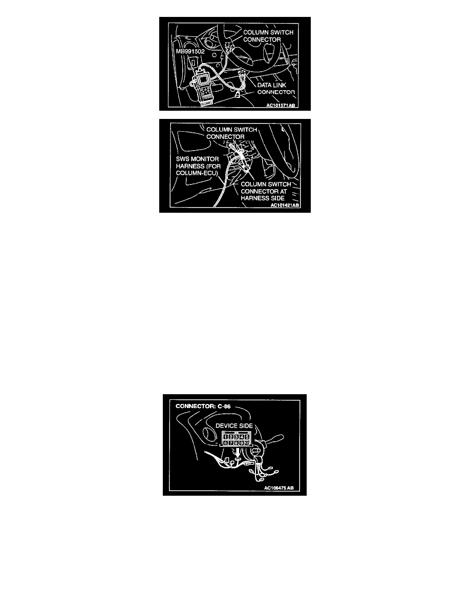
1. Connect scan tool MB991502 to the data link connector.
2. Connect SWS monitor kit MB991862 to the column switch connector.
3. Turn the ignition switch to the "LOCK" (OFF) position.
4. Operate the MUT-II according to the procedure below to display "ECU COMM CHECK."
1. Select "SYSTEM SELECT."
2. Select "SWS."
3. Select "SWS MONITOR."
4. Select "ECU COMM CHECK."
5. Scan tool MB991502 should show "OK" on the "ECU COMM CHECK" menu.
Q: Are "OK" displayed on the "ETACS ECU" and "COLUMN ECU" menus?
"OK" are displayed for all the items : Go to Step 2.
"NG" is displayed on the "COLUMN ECU" menu : "NG" is displayed on the "COLUMN ECU" menu: Refer to Inspection Procedure A-3
"Communication with ETACS-ECU is impossible."
"NG" is displayed on the "ETACS ECU" menu : "NG" is displayed on the "ETACS ECU" menu: Refer to Inspection Procedure A-3
"Communication with ETACS-ECU is impossible."
"NG" displayed on the "ETACS ECU" and "COLUMN ECU" menu. : "NG" are displayed for all the items: Refer to Inspection Procedure A-3
"Communication with ETACS-ECU is impossible."
STEP 2. Check column switch connector C-86 for damage.
Q: Is column switch connector C-86 in good condition?
YES: Go to Step 3.
NO: Repair or replace the connector. The system should communicate with the column switch (column-ECU) normally.
STEP 3. Check at column switch connector C-86 by backprobing in order to check the power supply circuit to the column switch (through the