
Eclipse V6-3.0L SOHC (2003)
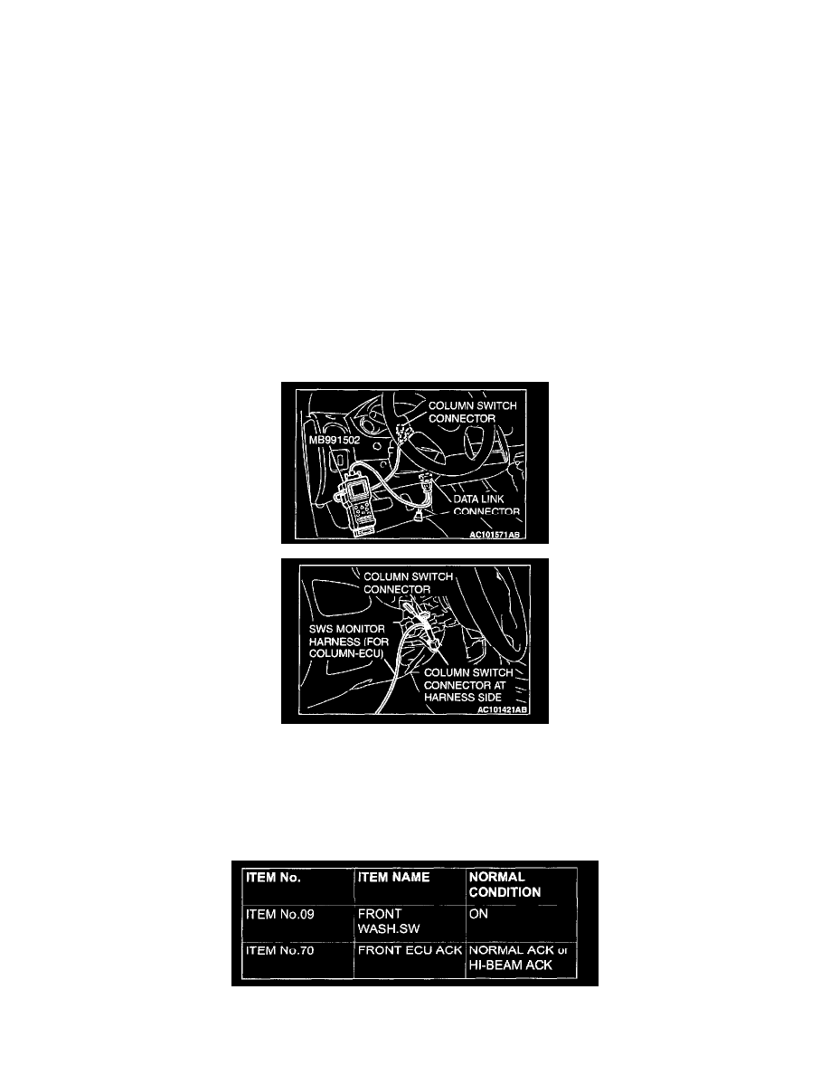
1. Connect scan tool MB991502 to the data link connector.
2. Connect SWS monitor kit MB991862 to the column switch connector.
3. Turn the ignition switch to the "ON" position.
4. Operate the MUT-II according to the procedure below to display "ECU COMM CHECK."
1. Select "SYSTEM SELECT."
2. Select "SWS."
3. Select "SWS MONITOR."
4. Select "ECU COMM CHECK."
5. Scan tool MB991502 should show "OK" on the "ECU COMM CHECK" menu.
Q: Are "OK" displayed on the "COLUMN ECU" and "FRONT ECU" menu?
"OK" are displayed for all the items : Go to Step 3.
"NG" is displayed on the "COLUMN ECU" menu : "NG" is displayed on the "COLUMN ECU" menu: Refer to Inspection Procedure A-2
"Communication with column switch (column-ECU) is impossible."
"NG" is displayed on the "FRONT ECU" menu : "NG" is displayed on the "FRONT ECU" menu: Refer to Inspection procedure A-4
"Communication with front-ECU is impossible."
STEP 3. Check the input signal by using "FUNCTION DIAGNOSIS" of the SWS monitor.
Check the input signals from the following switches:
-
Ignition switch: ON
-
Windshield washer switch: ON
Operate the MUT-II according to the procedure below to display "F.WIPER WASH."
1. Select "SYSTEM SELECT."
2. Select "SWS."
3. Select "SWS MONITOR."
4. Select "FUNCTION DIAGNOSIS"
5. Select "WIPER."
6. Select "F.WIPER WASH."
Check that normal conditions are displayed on the items described in the table.