
Eclipse V6-3.0L SOHC (2003)
"NG" is displayed on the "COLUMN ECU" menu : "NG" is displayed on the "COLUMN ECU" menu: Refer to Inspection Procedure A-2
"Communication with column switch (column-ECU) is impossible."
"NG" is displayed on the "FRONT ECU" menu : "NG" is displayed on the "FRONT ECU" menu: Refer to Inspection procedure A-4
"Communication with front-ECU is impossible."
STEP 2. Check the input signal by using "FUNCTION DIAGNOSIS" of the SWS monitor.
Check the input signals from the following switches:
-
Ignition switch: ON
-
Lighting switch: HEAD
Operate the MUT-II according to the procedure below to display "HEADLIGHT LO."
1. Select "SYSTEM SELECT."
2. Select "SWS."
3. Select "SWS MONITOR."
4. Select "FUNCTION DIAGNOSIS"
5. Select "LIGHTING."
6. Select "HEADLIGHT LO."
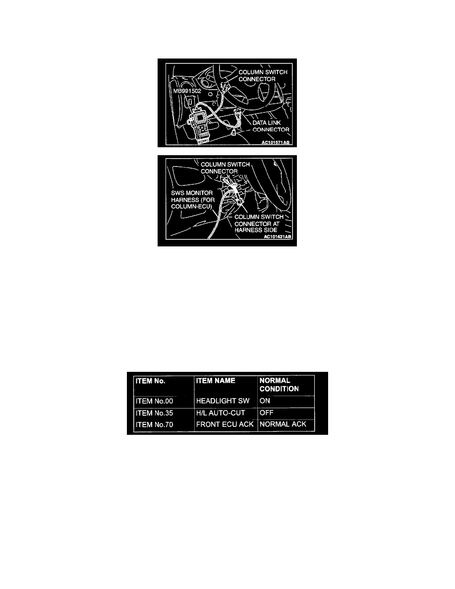
Check that normal conditions are displayed on the items described in the table.
Q: Does the scan tool display the items "HEADLIGHT SW", "H/L AUTO-CUT" and "FRONT ECU ACK" as normal condition?
YES: Go to Step 3.
NO:
-
The scan tool does not show the respective normal condition for item "HEADLIGHT SW." Refer to Inspection Procedure O-7 "ETACS-ECU
does not receive a signal from the headlight switch "
-
The scan tool does not show the respective normal condition for item "H/L AUTO-CUT." Refer to Inspection Procedure J-9 "Headlight automatic
shutdown function does not work normally "
-
The scan tool does not show the respective normal condition for item "FRONT ECU SW." Replace the ECU.Check that the headlights (low-beam)
illuminate normally.
STEP 3. Measure at front-ECU connector A-10X in order to check the battery circuit of power supply system to the front-ECU.