
Eclipse V6-3.0L SOHC (2003)
-
MB991223: Test Harness Set
-
MB991502: Scan Tool (MUT-II)
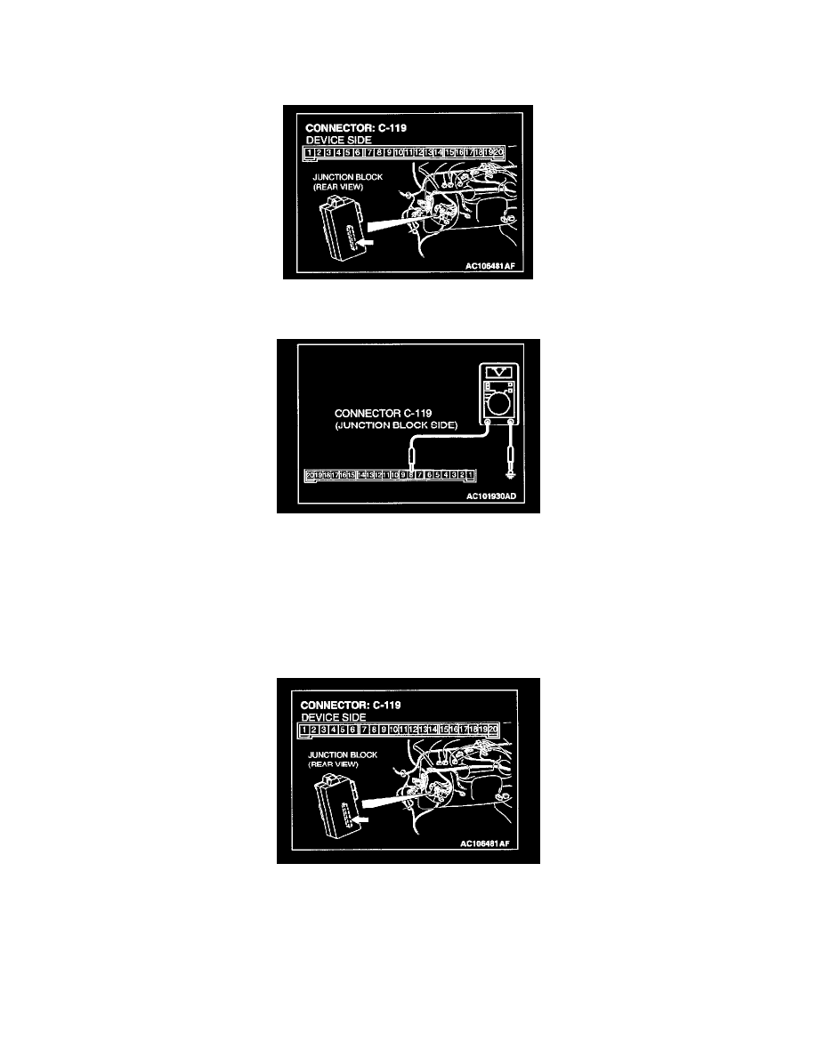
STEP 1. Measure at ETACS-ECU connector C-119 in order to check the line from the ignition switch (IG1) to the ETACS-ECU.
1. Disconnect ETACS-ECU connector C-119, and measure at the junction block side.
2. Turn the ignition switch to the "ON" position.
3. Measure the voltage between terminal 8 and ground.
-
The measured value should be approximately 12 volts (battery positive voltage).
Q: Does the measured voltage correspond with this range?
YES: Replace the ETACS-ECU. If the functions, which are described in "CIRCUIT OPERATION", work normally, the input signal from
the ignition switch (IG1) should be normal.
NO: Go to Step 2.
STEP 2. Check ETACS-ECU connector C-119 for damage.
Q: Is ETACS-ECU connector C-119 in good condition?
YES: Go to Step 3.
NO: Repair or replace the connector. Refer to Harness Connector Inspection. If the functions, which are described in "CIRCUIT OPERATION",
work normally, the input signal from the ignition switch (IG1) should be normal.