
Eclipse V6-3.0L SOHC (2003)
]]A[[ PRE-INSTALLATION INSPECTION
WARNING: Dispose of air bag modules only according to the specified procedure.
1. When installing the new air bag modules and clock spring, Refer to "INSPECTION."
2. Connect the negative (-) battery cable.
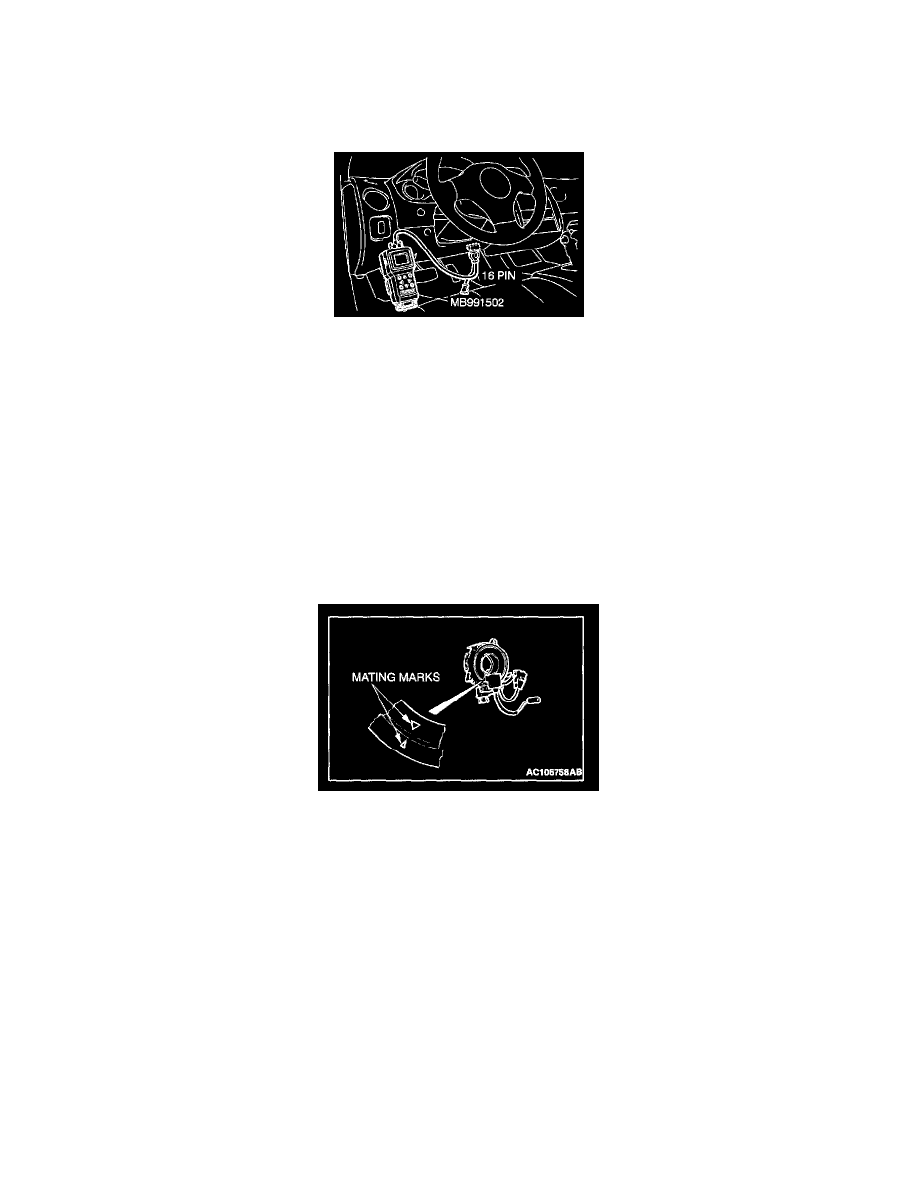
CAUTION: To prevent damage to scan tool MB991502, always turn the ignition switch to the "LOCK" (OFF) position before connecting or
disconnecting scan tool MB991502.
3. Connect scan tool MB991502 to the data link connector.
4. Turn the ignition switch to the "ON" position.
5. Conduct diagnostic test using scan tool MB991502 to ensure entire SRS operates properly.
DANGER: Wait at least 60 seconds after disconnecting the battery cable before doing any further work.
WARNING: Battery posts, terminals and related accessories contain lead and lead compounds. WASH HANDS AFTER HANDLING.
6. Turn the ignition switch to the "LOCK" (OFF) position. Disconnect the negative (-) battery cable and tape the terminal to prevent accidental
connection and air bags deployment.
]]B[[ CLOCK SPRING INSTALLATION
WARNING: Ensure that the clock spring's mating marks are properly aligned. If not, the steering wheel may not rotate completely during a
turn, or the flat cable in the clock spring could be damaged. This would prevent normal SRS operation and possibly cause serious injury to the
driver.
Align the mating marks of the clock spring. Turn the front wheels to the straight-ahead position. Then install the clock spring to the column switch.
<Mating Mark Alignment>
Turn the clock spring clockwise fully. Then turn it back approximately 3 turns counterclockwise to align the mating marks.
]]C[[ STEERING WHEEL INSTALLATION
CAUTION: When installing the steering wheel, ensure that the harness of the clock spring does not become caught or tangled.
1. Before installing the steering wheel, turn the vehicle's front wheels to the straight-ahead position and align the mating marks of the clock spring.