
Eclipse FWD L4-1997cc 2.0L DOHC MFI (1997)
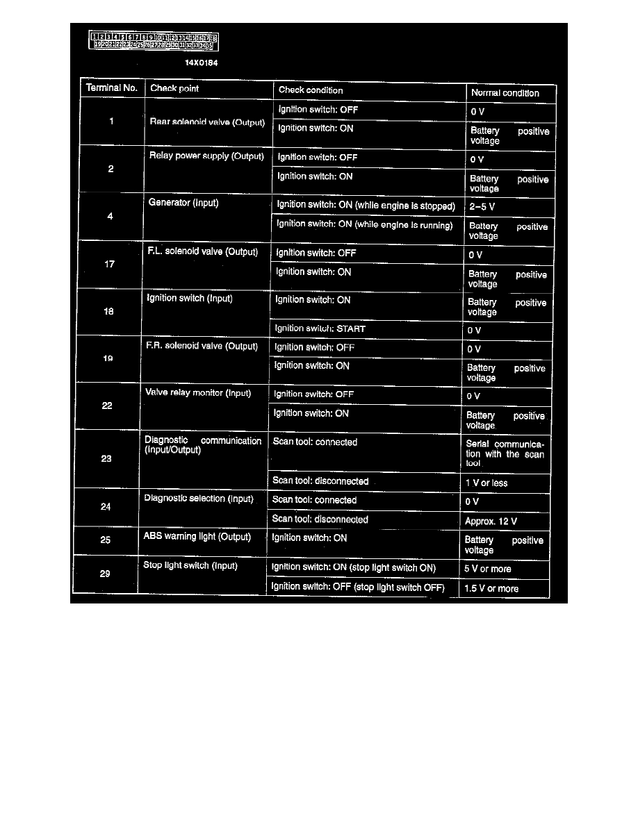
Terminal Voltage Check Chart
NOTE:
-
Measure voltage with the ABS-ECU connectors connected.
-
You may find it convenient to pull out the ABS-ECU to make it easier to reach the connector terminals.
-
Checks don't have to be carried out in the order given in the chart.
1. Connect a needle-nosed wire probe (paper clip etc.) to a voltmeter probe.
2. Insert the needle-nosed wire probe into each of the ABS-ECU connector terminals from the wire side, and measure the voltage while referring to
the check chart.
Caution: Short-circuiting the positive (+) probe between a connector terminal and ground could damage the vehicle wiring, the sensor,
ABS-ECU, or all three. Use care to prevent this.
3. If voltmeter shows any division from standard value, check the corresponding sensor, actuator and related electrical wiring, then repair or replace.