
Eclipse RS L4-2350cc 2.4L SOHC MFI (2002)
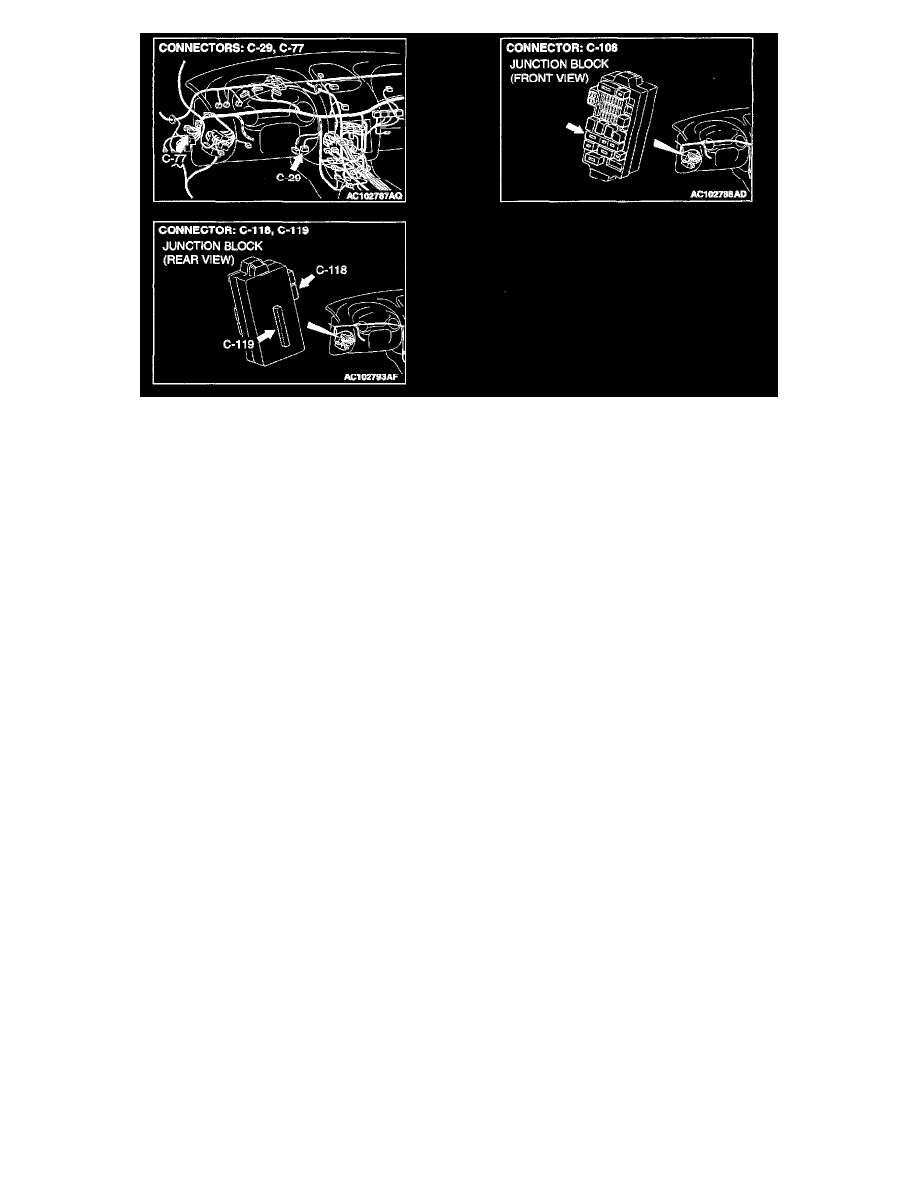
Connectors
TECHNICAL DESCRIPTION (COMMENT)
The SWS monitor kit may be connected improperly.
TROUBLESHOOTING HINTS
-
Malfunction of the SWS monitor body (I/F cartridge)
-
Malfunction of the SWS monitor harness-Malfunction of the ETACS-ECU
-
Damaged harness wires or connectors
DIAGNOSIS
Required Special Tools:
-
MB991223: Test Harness Set
-
MB991502: Scan Tool (MUT-II)
-
MB991862: SWS Monitor Kit
STEP 1. Check SWS monitor kit MB991B62 for proper connection.
Q: Is SWS monitor kit MB991862 connected with the column switch properly?
YES: Go to Step 2.
NO: Connect SWS monitor kit MB991862 to the column switch securely.
STEP 2. Check the power supply circuit to the ETACS-ECU.
Q: Does the system communicate with scan tool MB991502 when the ignition switch is turned to the "ON" position?
YES: Go to Step 3.
NO: Refer to Inspection Procedure A-3 "Communication with the ETACS-ECU is impossible."
STEP 3. Measure at ETACS-ECU connector C-119 in order to check the ground circuit to the ETACS-ECU.
1. Disconnect ETACS-ECU connector C-119, and measure at the junction block side.