
Eclipse RS L4-2350cc 2.4L SOHC MFI (2002)
STEP 7. Check the input signal by using service data of the SWS monitor.
Check the input signals from the following switches:
-
Ignition switch: ON
-
Turn-signal light switch: RH
CAUTION: To prevent damage to scan tool MB991502, always turn the ignition switch to the "LOCK" (OFF) position before connecting or
disconnecting scan tool MB991502. Also connect SWS monitor kit MB991862 after turning on scan tool MB991502.
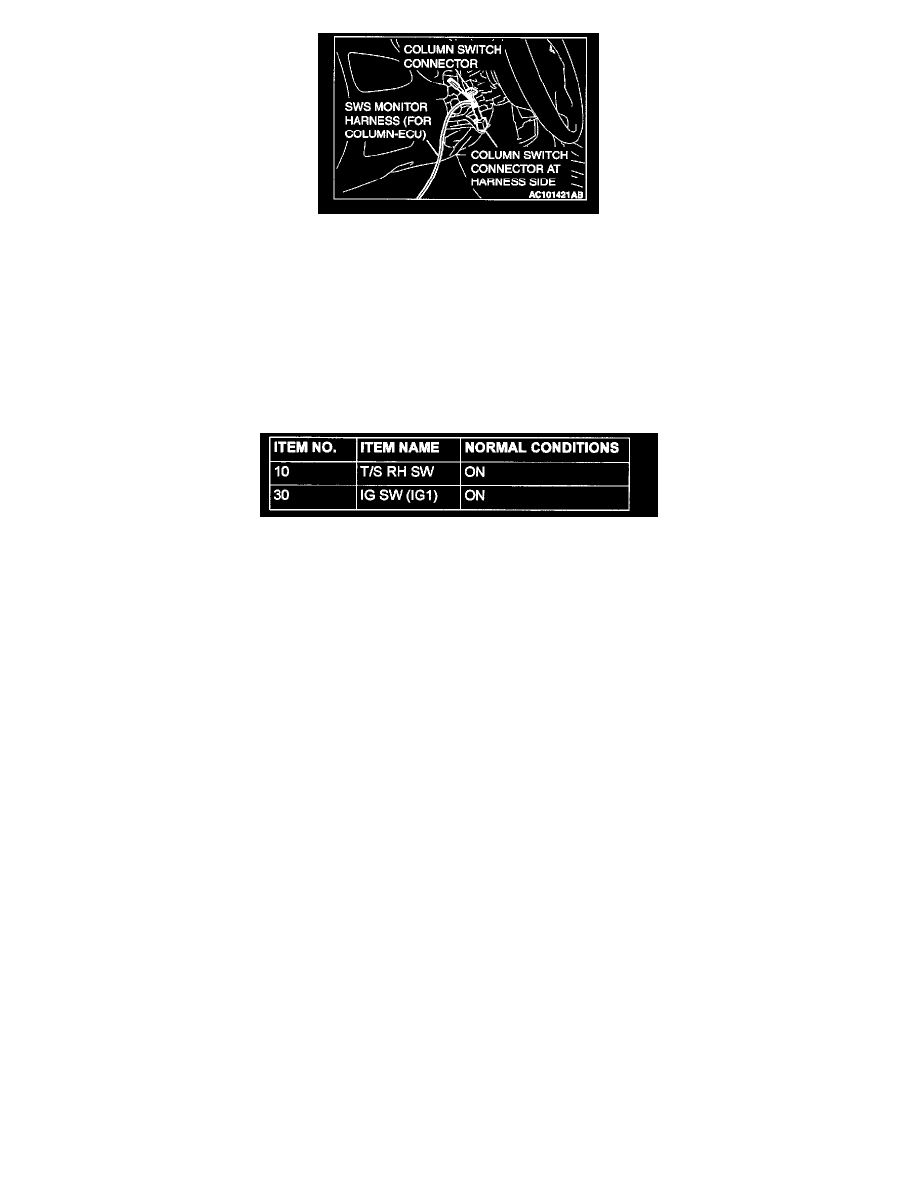
1. Connect scan tool MB991502 to the data link connector.
2. Connect SWS monitor kit MB991862 to the column switch connector.
3. Select "TURN SIGNAL - TURN SIG.RH" (FUNCTION DIAG.), and check that normal conditions are displayed on the items described in the
table.
Q: Does the scan tool display the items "T/S RH SW" and "IG SW (IG1)" as normal condition?
YES: Replace the ETACS-ECU. Check that the turn-signal lights illuminate normally.
NO:
-
The scan tool does not show the respective normal condition for item "T/S RH SW." Refer to Inspection Procedure O-7 "ETACS-ECU
does not receive any signal from the taillight switch, the headlight switch, the passing light switch, the dimmer switch, the turn-signal light
switch or switch."
-
The scan tool does not show the respective normal condition for item "IG SW(IG1)." Refer to Inspection Procedure O-2 "ETACS-ECU
does not receive a signal from the ignition switch (IG1)."
Inspection Procedure K-2
Flasher Timer: Hazard Warning Lights do not Illuminate.