
Eclipse RS L4-2350cc 2.4L SOHC MFI (2002)
YES: No action to be taken.
NO: Repair the wiring harness. If the functions or equipment, which are described in "CIRCUIT OPERATION", work normally, the interior light
loaded signal should be normal.
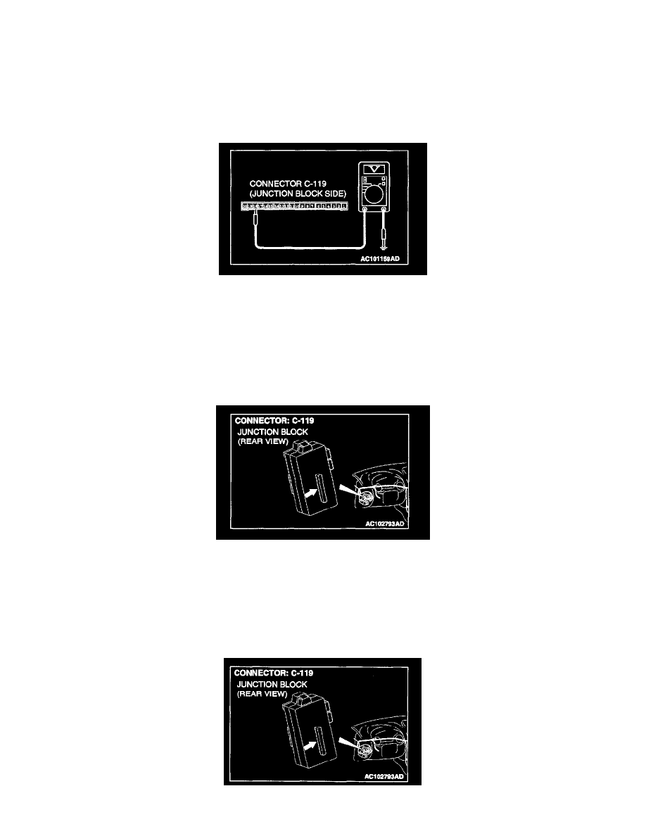
STEP 10. Measure at ETACS-ECU connector C-119 in order to check the ignition switch (ACC) line of the power supply to the ETACS-ECU.
1. Disconnect ETACS-ECU connector C-119, and measure at the junction block side.
2. Turn the ignition switch to the "ACC" position.
3. Measure the voltage between terminal 18 and ground.
-
The measured value should be approximately 12 volts (battery positive voltage).
Q: Does the measured voltage correspond with this range?
YES: Replace the ETACS-ECU. If the functions or equipment, which are described in "CIRCUIT OPERATION", work normally, the
interior light loaded signal should be normal.
NO: Go to Step 11.
STEP 11. Check ETACS-ECU connector C-119 for damage.
Q: Is ETACS-ECU connector C-119 in good condition?
YES: Go to Step 12.
NO: Repair or replace the connector. Refer to Harness Connector Inspection. If the functions or equipment, which are described in "CIRCUIT
OPERATION", work normally, the interior light loaded signal should be normal.