
Eclipse RS L4-2350cc 2.4L SOHC MFI (2002)
SRS Control Unit: Testing and Inspection
To inspect and service the SRS after a collision (whether or not the air bags have deployed), perform the following steps.
SRS-ECU MEMORY CHECK
Required Special Tool:
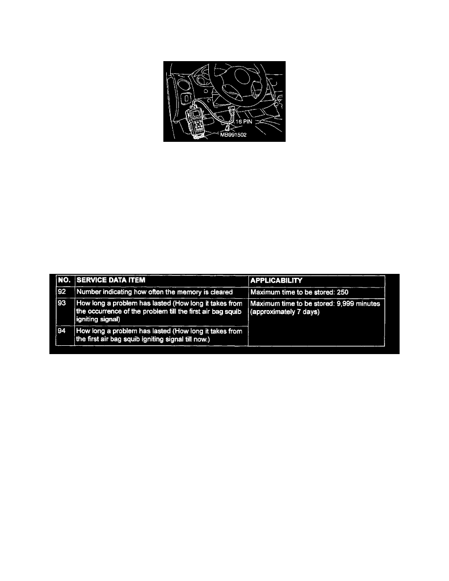
MB991502: Scan tool (MUT-II)
CAUTION: To prevent damage to scan tool MB991502, always turn the ignition switch to the "LOCK" (OFF) position before connecting or
disconnecting scan tool MB991502.
1. Connect scan tool MB991502 to the data link connector (16 pin).
NOTE: If the battery power supply has been disconnected or disrupted by the collision, scan tool MB991502 cannot communicate with the
SRS-ECU. Check the battery then check and, if necessary repair the front wiring harness and the instrument panel wiring harness before
proceeding.
2. Read (and write down) all displayed DTC.
Data List
3. Read the data list (fault duration and how many times memories are erased) using scan tool MB991502.
4. Erase the DTC and, after waiting 5 seconds or more, read (and write down) all displayed DTC.
SRS CONTROL UNIT (SRS-ECU) INSPECTION
WARNING: If a dent, crack, deformation or rust is discovered, replace the SRS-ECU with a new one.
-
Check the SRS-ECU and brackets for dents, cracks or deformation.
-
Check the SRS-ECU connector for damage, and the terminals for deformation.
NOTE: Refer to inspection of SRS-ECU for other than physical damage.