
Eclipse RS L4-2350cc 2.4L SOHC MFI (2002)
Ignition Switch: Electrical Diagrams
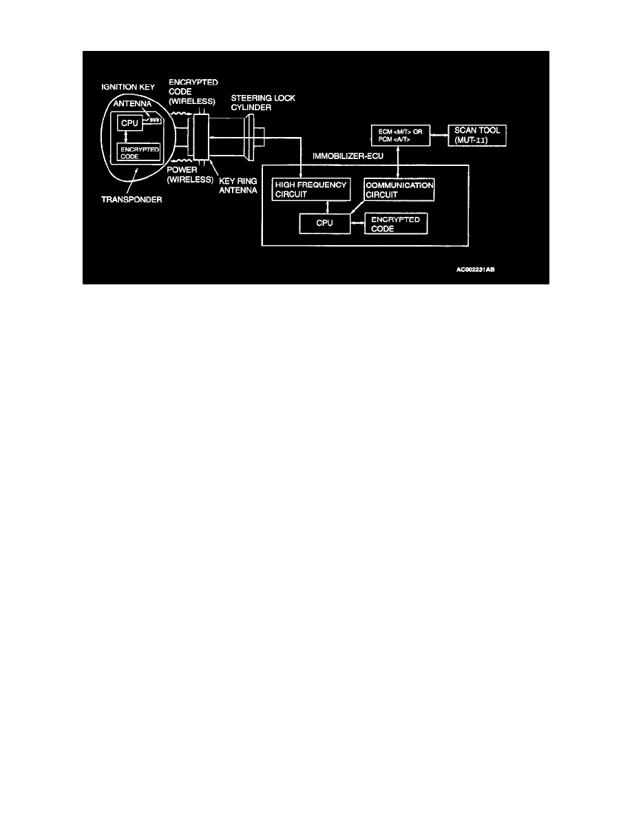
CONSTRUCTION DIAGRAM
CONSTRUCTION DIAGRAM
1. When the ignition switch is turned to "ON" position, the ECM <M/T> or PCM <A/T> sends a requirement for the encrypted code to the
immobilizer-ECU (at this time, the engine is remobilized).
2. When the immobilizer-ECU receives the requirement from the ECM <M/T> or PCM <A/T>, the immobilizer-ECU supplies power to the
transponder inside the ignition key via the antenna. The energized transponder sends the encrypted code back to the immobilizer-ECU via the
antenna.
3. The immobilizer-ECU judges the encrypted code with its code logic in itself. If they are identical, the immobilizer-ECU sends the encrypted code
to the ECM <M/T> or PCM <A/T>.
4. If the ECM <M/T> or PCM <AT> can not receive the encrypted code, the engine will be immobilized.