
Eclipse Spyder FWD L4-2350cc 2.4L SOHC 16 Valve (1996)
Reverse the removal procedure to install, noting the following:
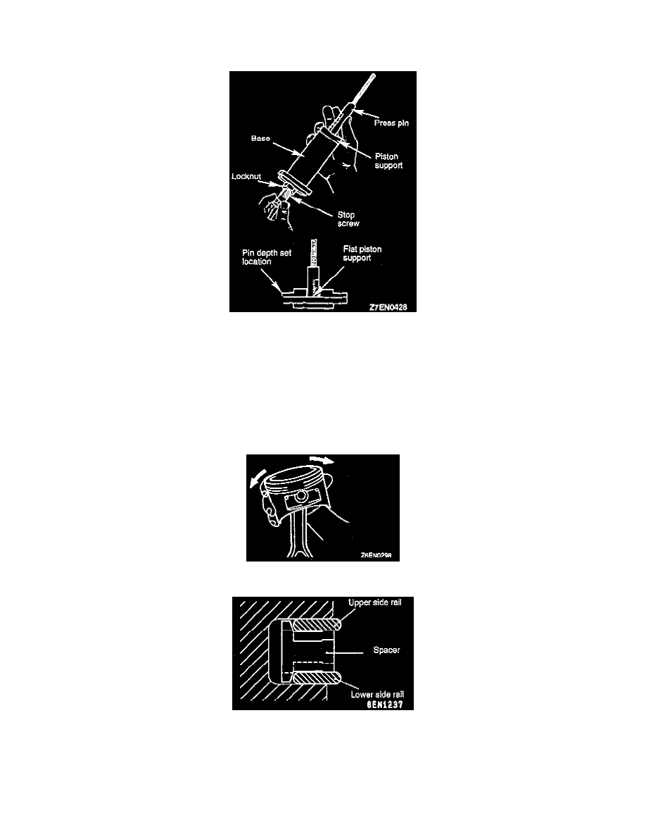
1. Thread the stop screw and lock nut assembly into the base. Fit the correct piston support on top of the base. Insert the press pin, threaded end up,
into the hole in the piston support until the press pin touches the stop screw.
2. Using the markings on the press pin, adjust the stop screw to the depth as shown. Regarding proper depth, refer to the operating instructions on the
special tool.
3. Place the base on press support blocks.
4. Slide the piston pin over the threaded end of the press pin, and thread the correct guide pin up against it.
5. Coat the piston pin with oil, and with the connecting rod held in position, slide the guide pin through the piston and connecting rod.
6. Press the piston pin through the connecting rod until the guide pin contacts the stop screw.
7. Remove the piston assembly from the base. Remove the guide pin and press pin from the assembly.
NOTE: Due to production tolerance variations, it is necessary to visually inspect the piston pin depth after installation to verify that the piston pin
is centered. Adjust if necessary.
8. Check that the piston moves smoothly.
9. Fit the oil ring spacer into the piston ring groove.
NOTE:
-
The side rails and spacer may be installed in either direction
-
New spacers and side rails are colored for identification of their sizes.
Standard: not colored
0.50 mm oversize: blue