
Eclipse Spyder GS L4-2350cc 2.4L SOHC MFI (2001)
STEP 3. Check the input signal (by using a voltmeter).
Check the input signal from the taillight switch.
1. Use special tool MB991529 to connect a voltmeter between ground terminal 4 or 5 and ETACS-ECU terminal 9 of the data link connector.
2. Check that the voltmeter indicator deflects once when the input signal enters.
Q: Does the voltmeter indicator deflect?
YES: Go to Step 4.
NO: Check the taillight switch input signal circuit. Refer to Inspection Procedure O-17.
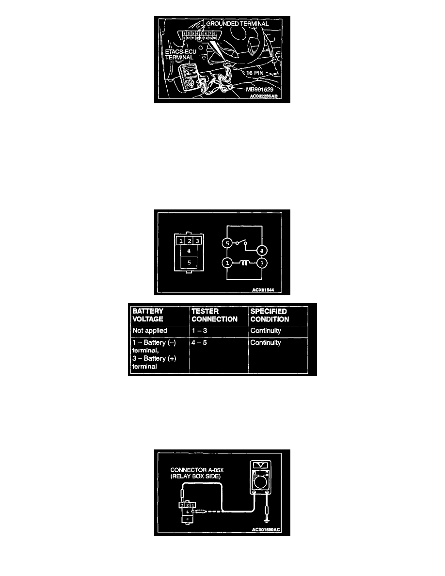
STEP 4. Check the taillight relay.
Q: Is the taillight relay in good condition?
YES: Go to Step 5.
NO: Replace it. The taillights should illuminate normally.
STEP 5. Check the taillight relay power supply circuit at the taillight relay connector A-05X.