
Eclipse Spyder GS L4-2350cc 2.4L SOHC MFI (2001)
disconnecting scan tool MB991502.
1. Connect scan tool MB991502 to the data link connector.
2. Check that the tone alarm of scan tool MB991502 sounds when the input signal enters.
Q: Does the tone alarm of scan tool MB991502 sound when the Input signal enters?
YES: Replace the front-ECU. The passing switch should work normally.
NO: Check the passing switch input circuit. Refer to Inspection Procedure O-17.
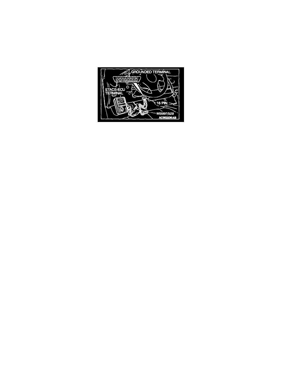
STEP 3. Check the Input signal (by using a voltmeter).
Check the input signal from the passing switch.
1. Use special tool MB991529 to connect a voltmeter between ground terminal 4 or 5 and ETACS-ECU terminal 9 of the data link connector.
2. Check that the voltmeter indicator deflects once when the input signal enters.
Q: Does the voltmeter indicator deflect?
YES: Replace the front-ECU. The passing switch should work normally.
NO: Check the passing switch input circuit. Refer to Inspection Procedure O-17.
Inspection Procedure J-5
Headlight, Taillight: High-Beam Indicator Light Does Not Illuminate