
Endeavor 2WD V6-3.8L SOHC (2006)
3. Measure the voltage between intermediate connector terminal 11 and body ground.
OK: 1.0 V or less
CAUTION: Strictly observe the specified wiring harness repair procedure.
Q: Does the voltage measure 1.0 V or less?
YES: <The voltage measures 1.0 V or less> Go to Step 29.
NO: <The voltage measures more than 1.0 V> Repair the wiring harness between intermediate connector C-31 and ASC/TCL-ECU connector.
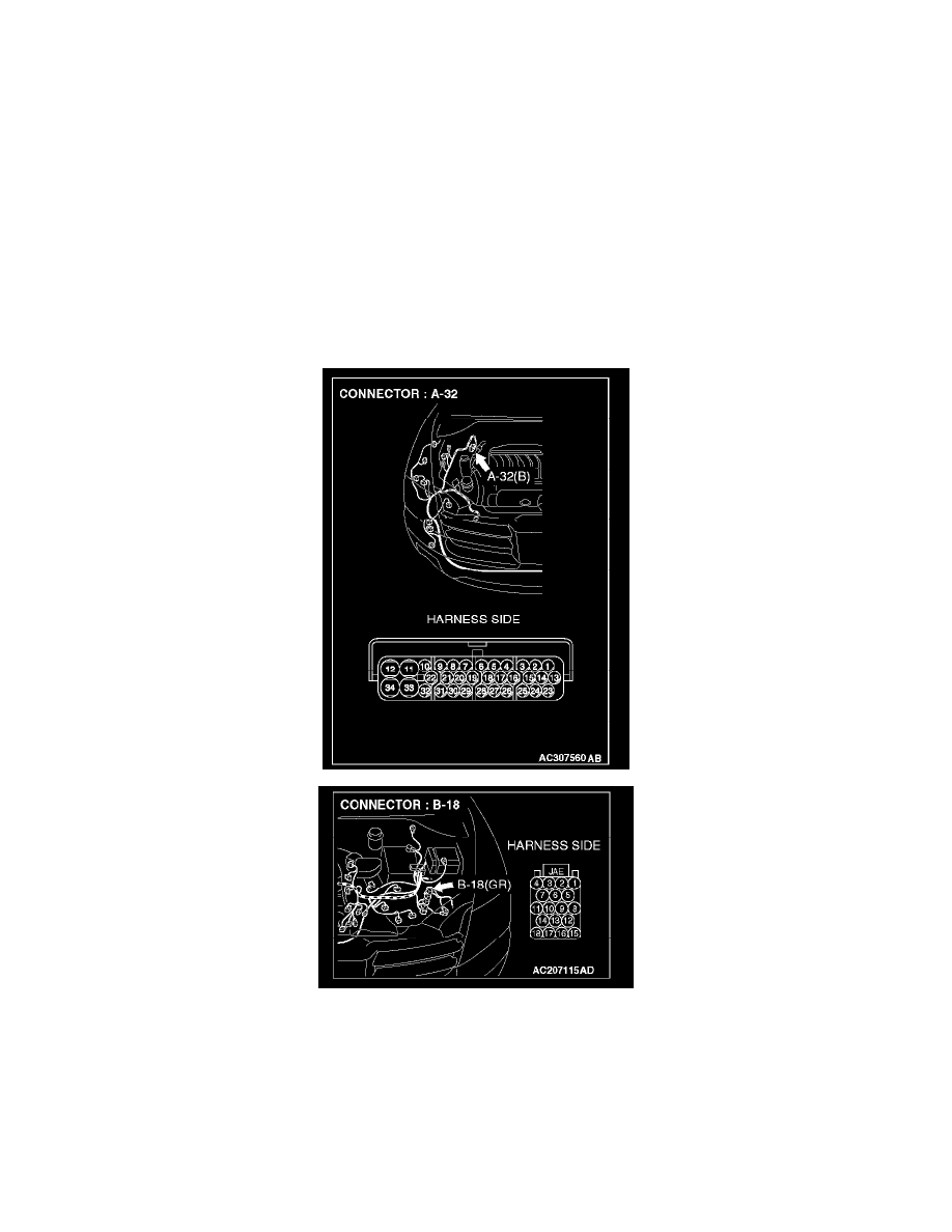
STEP 29. Check the CAN_H line (communication line only) between the powertrain control module connector and ASC/TCL-ECU connector
for a short to the power supply. Measure voltage at powertrain control module connector B-18.
CAUTION: A digital multimeter should be used.
CAUTION: The test wiring harness should be used.
1. Disconnect powertrain control module connector B-18 and ASC/TCL-ECU connector A-32, and measure the voltage at the harness side of
powertrain control module connector B-18.
2. Turn the ignition switch to the "ON" position.