
Endeavor 2WD V6-3.8L SOHC (2006)
-
MB991970: ABS Check Harness
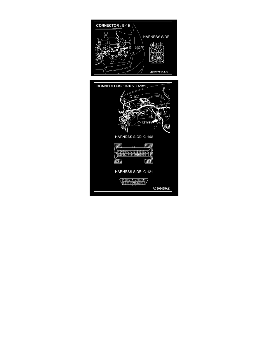
STEP 1. Check powertrain control module connector B-18, combination meter connector C-102 and data link connector C-121 for loose,
corroded or damaged terminals, or terminals pushed back in the connector.
CAUTION: The strand end of the twist wire should be within 10 cm (4 inches) from the connector.
Q: Are powertrain control module connector B-18, combination meter connector C-102 and data link connector C-121 in good condition?
YES: Go to Step 2.
NO: Repair the damaged parts.
STEP 2. Check the CAN_H-side bus line (communication line including ECUs) for short to ground. Measure the resistance at data link
connector C-121.
CAUTION: A digital multimeter should be used.
CAUTION: The test wiring harness should be used.