
Endeavor 2WD V6-3.8L SOHC (2006)
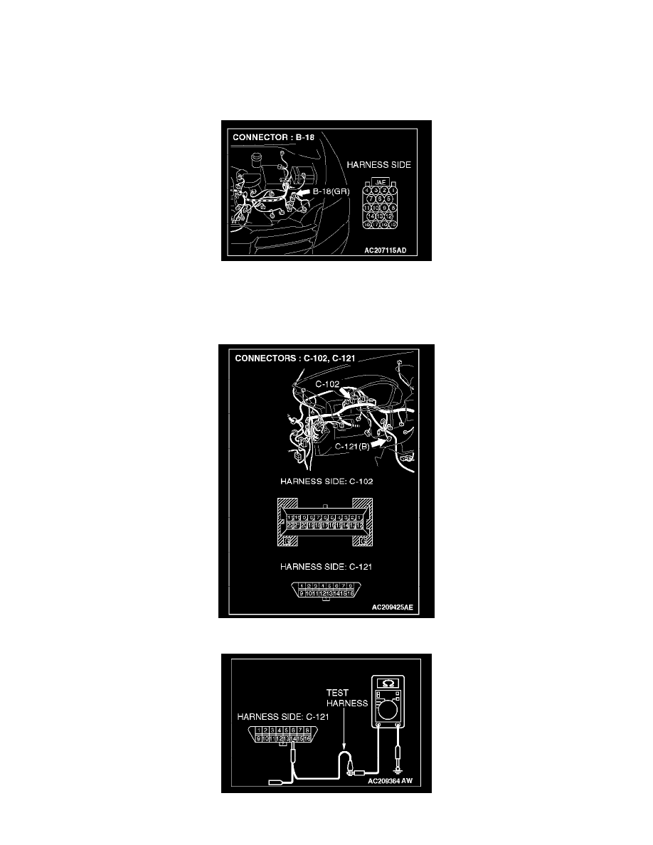
STEP 3. Check the CAN_L-side bus line (communication line including ECUs) for short to ground. Measure the resistance at data link
connector C-121.
CAUTION: A digital multimeter should be used.
CAUTION: The test wiring harness should be used.
1. Disconnect powertrain control module connector B-18 and combination meter connector C-102, and measure the resistance at the harness side of
data link connector C-121.
2. Turn the ignition switch to the "LOCK" (OFF) position.
CAUTION: Disconnect the negative battery terminal.
3. Disconnect the negative battery terminal.
4. Measure the resistance between data link connector terminal 14 and body ground.