
Endeavor 2WD V6-3.8L SOHC (2006)
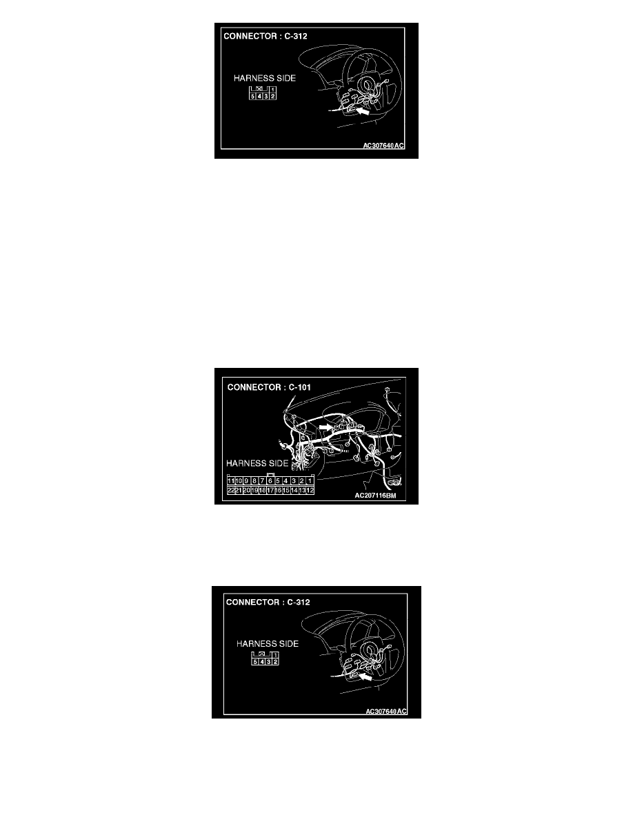
STEP 50. Check steering wheel sensor connector C-312 for loose, corroded or damaged terminals, or terminals pushed back in the connector.
CAUTION: The strand end of the twist wire should be within 10 cm (4 inches) from the connector.
Q: Is steering wheel sensor connector C-312 in good condition?
YES: Go to Step 51.
NO: Repair the damaged parts.
STEP 51. Check the CAN_L line (communication line only) between joint connector (4) and steering wheel sensor connector for short to
ground. Measure the resistance at joint connector (4) C-101.
CAUTION: A digital multimeter should be used.
CAUTION: The test wiring harness should be used.
1. Disconnect joint connector (4) C-101 and steering wheel sensor connector C-312, and measure the resistance at the wiring harness side of joint
connector (4) C-101.
2. Turn the ignition switch to the "LOCK" (OFF) position.
CAUTION: Disconnect the negative battery terminal.
3. Disconnect the negative battery terminal.