
Endeavor 2WD V6-3.8L SOHC (2006)
4. Measure the resistance between joint connector (4) terminal 15 and body ground.
OK: 1 kOhm or more
CAUTION: Strictly observe the specified wiring harness repair procedure.
Q: Does the resistance measure 1 kOhm or more?
YES: <The resistance measures 1 kOhm or more> Diagnose CAN bus lines thoroughly by referring to DIAGNOSTIC ITEM 30: Diagnose CAN
bus lines thoroughly <Vehicles with ASC and vehicles with multi-center display (middle-grade type)>.
NO: <The resistance measures less than 1 kOhm> Repair the wiring harness between joint connector (4) and the combination meter connector.
STEP 9. Check the CAN_H line (communication line including the ETACS-ECU) between joint connector (4) and the ETACS-ECU connector
for short to ground. Measure the resistance at joint connector (4) C-101.
CAUTION: A digital multimeter should be used.
CAUTION: The test wiring harness should be used.
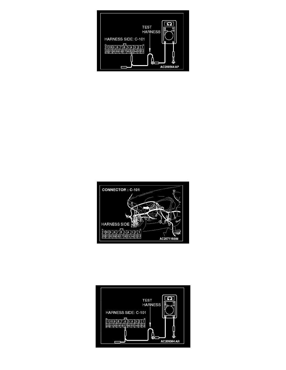
1. Disconnect joint connector (4) C-101, and measure the resistance at the wiring harness side of joint connector (4) C-101.
2. Turn the ignition switch to the "LOCK" (OFF) position.
CAUTION: Disconnect the negative battery terminal.
3. Disconnect the negative battery terminal.
4. Measure the resistance between joint connector (4) terminal 17 and body ground.