
Endeavor 2WD V6-3.8L SOHC (2006)
2. Measure the resistance between the multi-center display unit (middle-grade type) connector terminals 12 and 13.
OK: 1 kOhm or more
Q: Does the resistance measure 1 kOhm or more?
YES: <The resistance measures 1 kOhm or more> Diagnose CAN bus lines thoroughly by referring to DIAGNOSTIC ITEM 28: Diagnose CAN
bus lines thoroughly <Vehicles with ABS without ASC and vehicles with multi-center display (middle-grade type)>.
NO: <The resistance measures lower than 1 kOhm> Replace the multi-center display unit (middle-grade type).
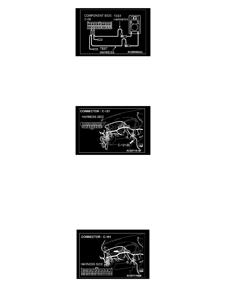
STEP 24. Check data link connector C-121 for loose, corroded or damaged terminals, or terminals pushed back in the connector.
CAUTION: The strand end of the twist wire should be within 10 cm (4 inches) from the connector.
Q: Is data link connector C-121 in good condition?
YES: Go to Step 25.
NO: Repair the damaged parts.
STEP 25. Check the CAN_L and H lines (communication lines only) between joint connector (4) and the data link connector for short circuit.
Measure the resistance at joint connector (4) C-101.
CAUTION: A digital multimeter should be used.
CAUTION: The test wiring harness should be used.