
Endeavor 2WD V6-3.8L SOHC (2006)
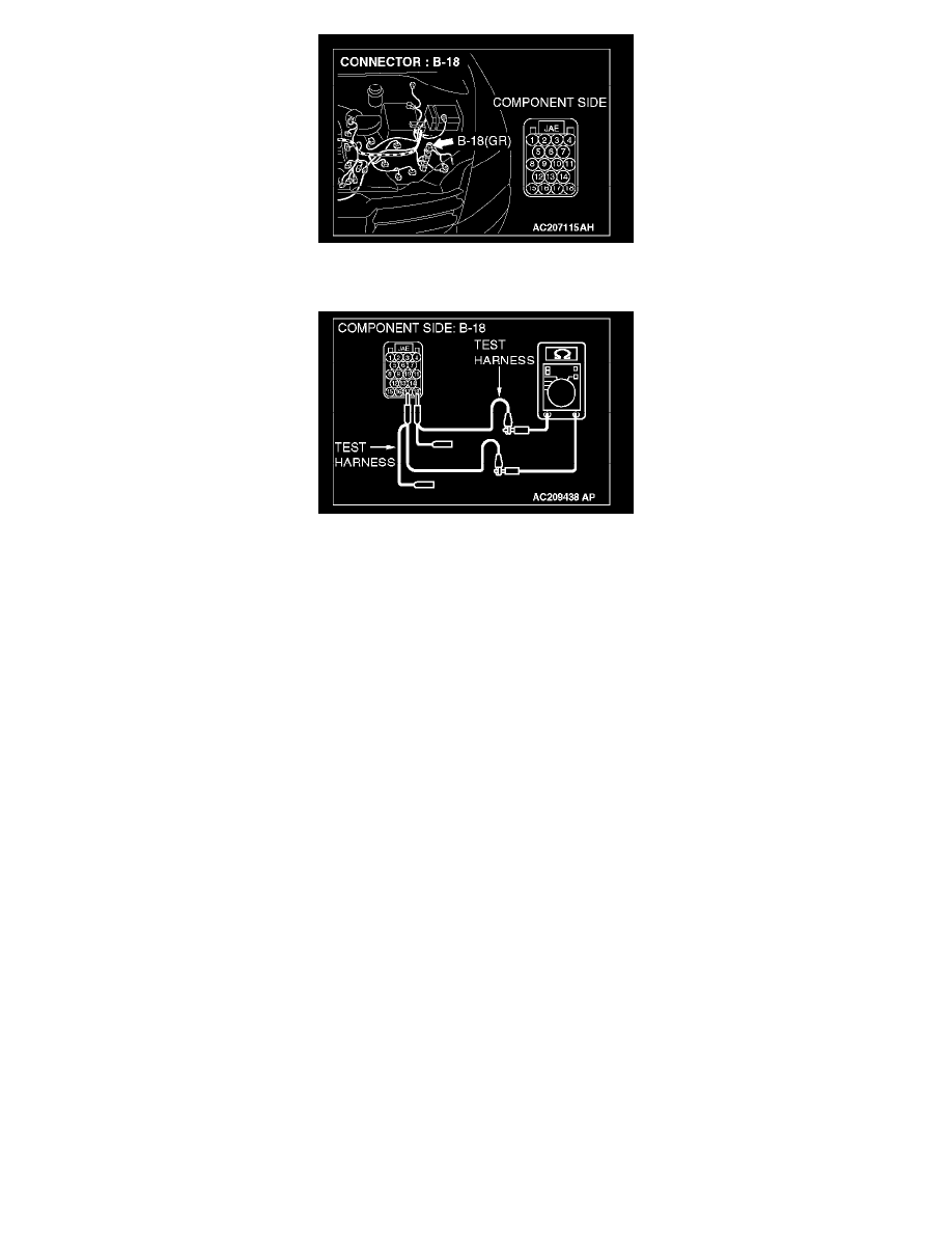
1. Disconnect powertrain control module connector B-18, and measure the resistance at the equipment side of powertrain control module connector
B-18.
2. Measure the resistance between powertrain control module connector terminals 17 and 18.
OK: 120 ± 20 Ohms
Q: Does the resistance measure 120 ± 20 Ohms?
YES: <The resistance measures 120 ± 20 Ohms> Diagnose CAN bus lines thoroughly by referring to DIAGNOSTIC ITEM 29: Diagnose CAN
bus lines thoroughly <Vehicles with ASC and vehicles without multi-center display (middle-grade type)>.
NO: <The resistance does not measure 120 ± 20 Ohms> Replace the powertrain control module.
Part 1
DIAGNOSTIC ITEM 18: Diagnose shorts between CAN_L and H lines <Vehicles with ASC and vehicles with multi-center display
(middle-grade type)>