
Endeavor 2WD V6-3.8L SOHC (2006)
NO: Repair the damaged parts.
STEP 34. Check the CAN_L and H lines (communication lines only) between joint connector (4) and the data link connector for short circuit.
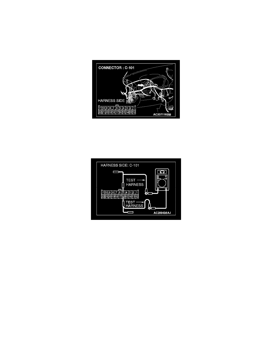
Measure the resistance at joint connector (4) C-101.
CAUTION: A digital multimeter should be used.
CAUTION: The test wiring harness should be used.
1. Disconnect joint connector (4) C-101, and measure the resistance at the wiring harness side of joint connector (4) C-101.
2. Turn the ignition switch to the "LOCK" (OFF) position.
CAUTION: Disconnect the negative battery terminal.
3. Disconnect the negative battery terminal.
4. Measure the resistance between joint connector (4) terminals 5 and 16.
OK: 1 kOhm or more
Q: Does the resistance measure 1 kOhm or more?
YES: <The resistance measures 1 kOhm or more> Go to Step 35.
NO: <The resistance measures less than 1 kOhm> Repair the wiring harness between joint connector (4) and the data link connector.
STEP 35. Check the CAN_L and H lines (communication lines only) between joint connector (4) and the intermediate connector for short
circuit. Measure the resistance at joint connector (4) C-101.
CAUTION: A digital multimeter should be used.
CAUTION: The test wiring harness should be used.