
Endeavor 2WD V6-3.8L SOHC (2006)
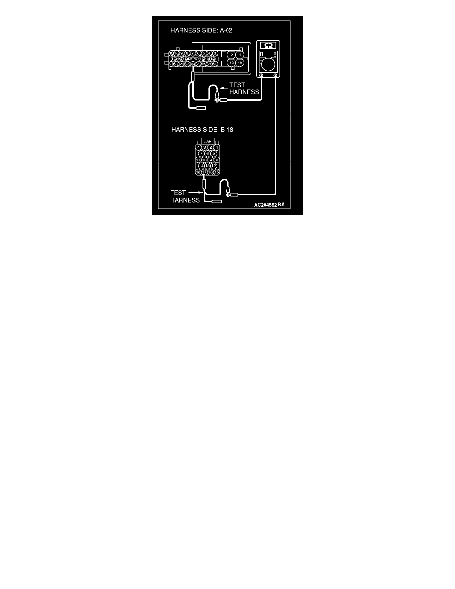
5. Measure the resistance between ABS-ECU <Vehicles without TCL> or ABS/TCL-ECU <Vehicles with TCL> connector terminal 24 and
powertrain control module connector terminal 17.
OK: 2 Ohms or less
CAUTION: Strictly observe the specified wiring harness repair procedure.
Q: Do all the resistances measure 2 Ohms or less?
YES: <All the resistances measure 2 Ohms or less> Go to Step 24.
NO: <If either of the resistances measures more than 2 Ohms or all the resistances measure more than 2 Ohms> Repair the wiring harness
between ABS-ECU <Vehicles without TCL> or ABS/TCL-ECU <Vehicles with TCL> connector and the powertrain control module connector.
STEP 24. Check the CAN bus lines inside the ABS-ECU <Vehicles without TCL> or ABS/TCL-ECU <Vehicles with TCL>. Measure the
resistance at ABS-ECU <Vehicles without TCL> or ABS/TCL-ECU <Vehicles with TCL> connector A-02.
CAUTION: A digital multimeter should be used.
CAUTION: The test wiring harness should be used.