
Endeavor 2WD V6-3.8L SOHC (2006)
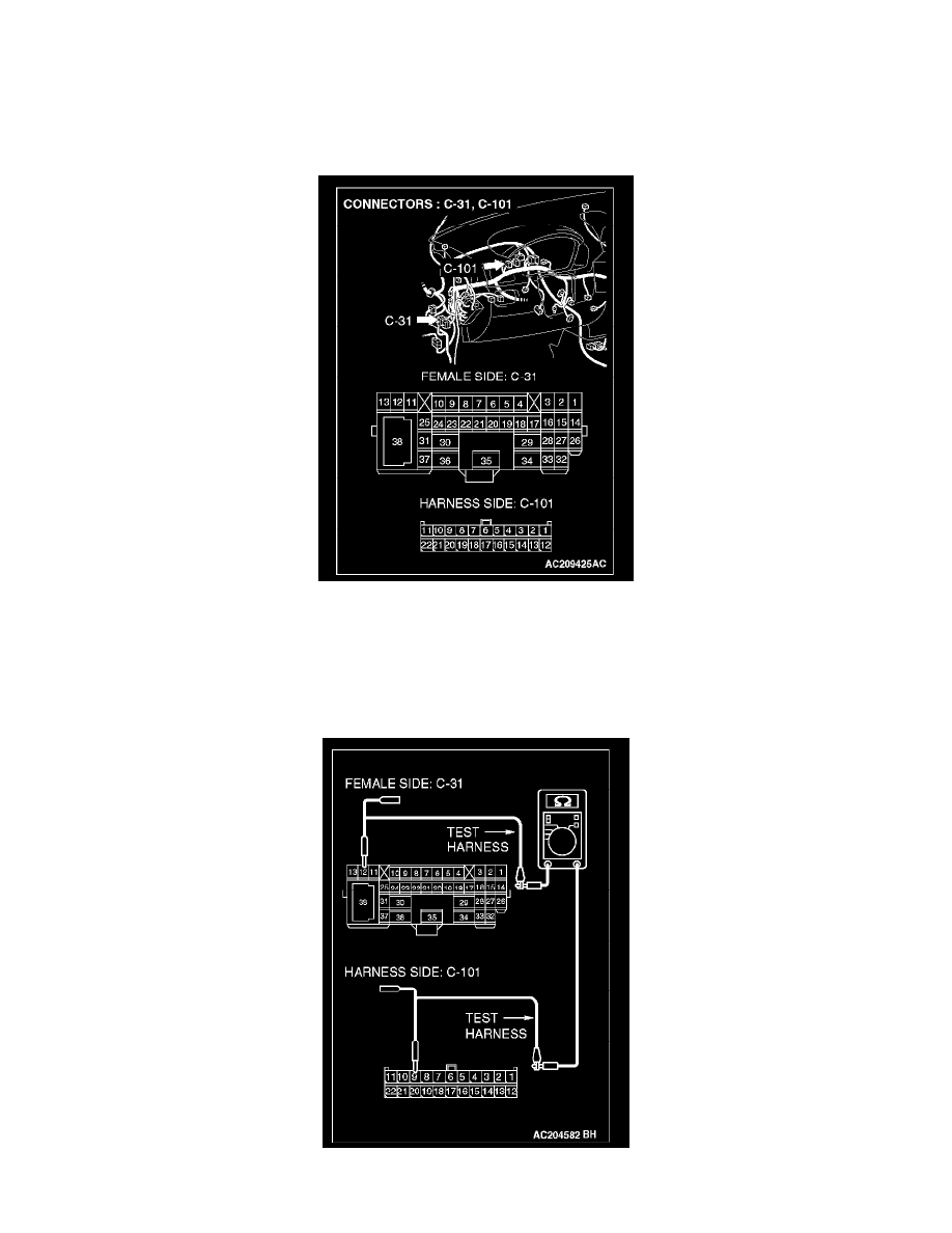
STEP 3. Check the CAN bus lines between intermediate connector C-31 and the joint connector (4). Measure the resistance between
intermediate connector C-31 and joint connector (4) C-101.
CAUTION: A digital multimeter should be used.
CAUTION: The test wiring harness should be used.
1. Disconnect joint connector (4) C-101 and intermediate connector C-31, and measure the resistance between the wiring harness side connector of
joint connector (4) C-101 and the female side connector of intermediate connector C-31 (instrument panel wiring harness side).
2. Turn the ignition switch to the "LOCK" (OFF) position.
CAUTION: Disconnect the negative battery terminal.
3. Disconnect the negative battery terminal.
4. Measure the resistance between joint connector (4) terminal 9 and intermediate connector terminal 12.