
Endeavor 2WD V6-3.8L SOHC (2006)
conditioning system> in good condition?
YES: Go to Step 2.
NO: Repair the damaged parts. Replace the joint connector as necessary.
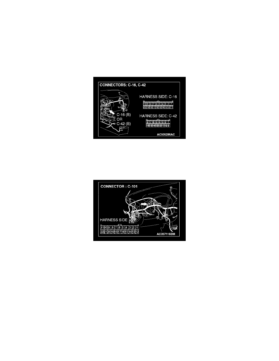
STEP 2. Check the CAN bus lines between joint connector (4) and the A/C-ECU. Measure the resistance between joint connector (4) C-101 and
A/C-ECU connector C-42 <manual air conditioning system> or A/C-ECU connector C-16 <automatic air conditioning system>.
CAUTION: A digital multimeter should be used.
CAUTION: The test wiring harness should be used.
1. Disconnect joint connector (4) C-101 and A/C-ECU connector C-42 <manual air conditioning system> or A/C-ECU connector C-16 <automatic
air conditioning system>, and measure the resistances at the wiring harness sides of joint connector (4) C-101 and A/C-ECU connector C-42
<manual air conditioning system> or A/C-ECU connector C-16 <automatic air conditioning system>.
2. Turn the ignition switch to the "LOCK" (OFF) position.
CAUTION: Disconnect the negative battery terminal.
3. Disconnect the negative battery terminal.