
Expo LRV AWD L4-2350cc 2.4L SOHC 16 Valve (1993)
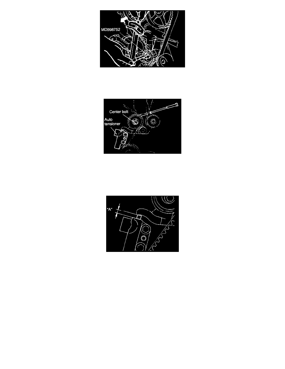
2. Loosen the center bolt, and then, as shown in the illustration, attach the special tool and a torque wrench and apply a torque of 3.6 Nm (2.6 ft.lbs.).
If the body interferes with the special tool and the torque wrench, use a jack to slightly raise the engine assembly.
NOTE: Use a torque wrench that is capable of measurement within a range of 0 - 5 Nm (0 - 3.7 ft.lbs.).
3. Holding the tensioner pulley with the special tool and torque wrench, tighten the center bolt to the specified torque.
4. Screw the tool into the engine left support bracket until its end touch the tensioner arm. At that point, screw the tool in some more and then remove
the set wire attached to the auto tensioner.
5. Remove the tool.
6. Rotate the crankshaft two complete turns clockwise and leave it as is for about 15 minutes. Then, measure the auto tensioner protrusion "A"
(distance between the tensioner arm and auto tensioner body).
Standard value: 3.8 - 4.5 mm (0.15 - 0.18 in.)
NOTE: If it is not within the standard value, repeat steps "1" through "6" until the specified value is obtained.
7. If the clearance between the tensioner arm and the auto tensioner body cannot be measured (when the engine is being mounted, etc.), the following
procedures can be used to substitute for the ordinary method of measurement.