
Expo LRV AWD L4-2350cc 2.4L SOHC 16 Valve (1993)
14. Remove the shaft bearing tightening screws.
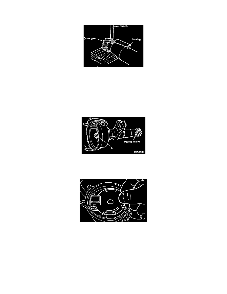
15. Make a position identification mark on the distributor shaft (for the drive gear, to prevent 180° out of alignment, reassembly).
16. Place the drive gear on a soft base (wooden block) so that it will not be damaged.
Distributor Drive Gear Removal
17. Drive out the roll pin by using a pin punch.
18. Remove crankshaft position/camshaft (TDC) sensor hold down screws. Replace crankshaft/TDC sensor module.
REASSEMBLY:
19. After coating the shaft with a small amount of engine oil, insert the shaft into the distributor housing.
CAUTION: Do not use solvent or similar products.
20. Align the drive gear with the mark made at the time of disassembly, and install the gear to the distributor shaft.
21. When aligning the drive gear's mating mark to the housing's mark, be sure that the notch "A" at the rotor end of the shaft is in the position shown in
Fig. 1. If no errors where made in either the marking or alignment procedures the pin holes should align properly. Drive in a new roll pin, insuring
that the slit in the pin is at a 90° to the distributor shaft.
Disc Installation Procedure
22. Install the spacer on the distributor shaft.
23. Insert the disc into the sensor part of the pick up unit assembly insuring the proper alignment with the notch on the spacer.
NOTE:Take care to install the disc with the correct side to the top as was observed during disassembly. Insure that the disc is clean and that the
disc's slits are clear of any foreign matter.
24. Install the rotor shaft and its retaining screw.