
Expo LRV AWD L4-2350cc 2.4L SOHC 16 Valve (1993)
Crankshaft Position Sensor: Component Tests and General Diagnostics
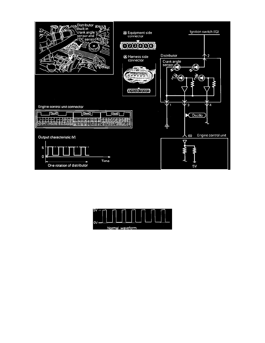
Crank Angle Sensor Circuit
To test the Crank Angle Sensor located in the distributor, proceed as follows
OSCILLOSCOPE TESTING PROCEDURE:
1. Connect test leads from the oscilloscope to the #3 terminal of the sensor connector and run the engine at idle speed.
Scope Pattern
2. Check the waveform and compare it to the diagram shown.
If scope pattern is not as depicted in image, continue with the rest of the test procedures before replacing the assembly.
VOLTAGE TESTING PROCEDURE:
1. Connect an analog voltmeter between terminal 1 and 3 of the crank angle sensor connector.
Terminal 3: Crankshaft Position signal
Terminal 1: Sensor ground
2. Measure the output voltage of the terminals while cranking the engine.
Standard Approximate Values
1.8 - 2.5v (needle fluctuates)
3. When the voltage is abnormal, check the sensor power and ground circuits.
HARNESS TEST:
1. Disconnect the crankshaft position/camshaft (TDC) sensor connector and turn the key to the ON position.
2. Using a voltmeter, measure the power supply voltage between the harness connector terminal 2 and ground.