
Expo LRV AWD L4-2350cc 2.4L SOHC 16 Valve (1993)
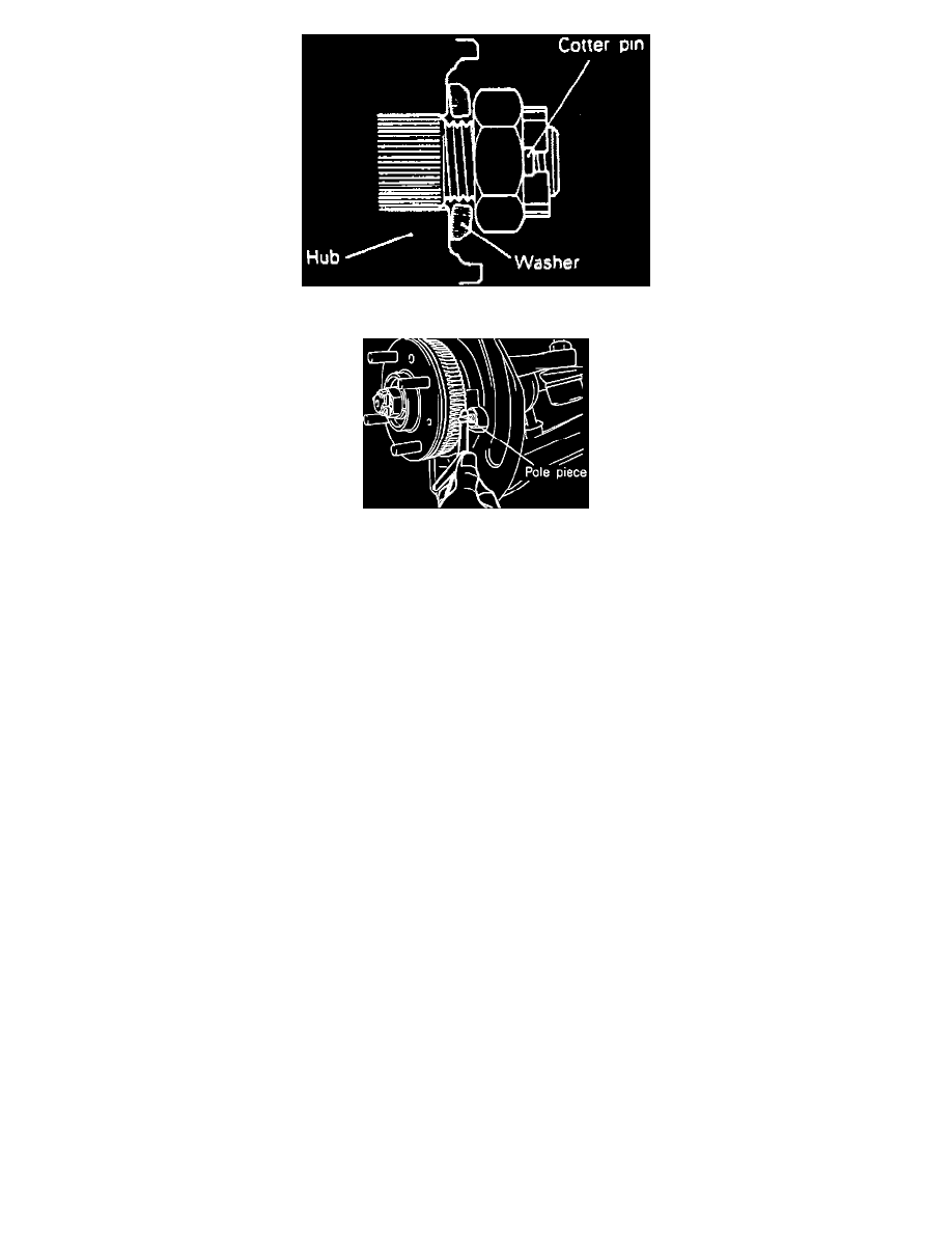
Fig. 3 Washer Installation
Fig. 9 Checking Speed Sensor Pole Piece Clearance. (Models W/ABS)
1.
Replace hub, knuckle and bearing in numbered sequence shown in Figs. 6 and 7, noting the following:
a. Remove caliper and suspend with wire, then remove driveshaft nut using end yoke holder MB990767-01 or equivalent.
b. Disconnect ball joint and tie rod end using steering linkage puller MB990635-01 or equivalent. Loosen, but do not remove ball joint and
tie rod end nuts until knuckle is ready to be removed.
c. Using a suitable axle shaft puller, press driveshaft from front hub.
d. Ensure driveshaft nut and washer are installed in direction shown in Fig. 8.
e. Temporarily install speed sensor to knuckle, if equipped, then insert a suitable thickness gauge between sensor pole piece and rotor toothed
surface, Fig. 9, and tighten speed sensor at a position where clearance is .012-0.035 inch. If clearance cannot be obtained, check for
improper installation of rotor.
f.
Remove hub by attaching front hub remover/installer MB990998-01 and knuckle arm bridge MB991355 or their equivalents to knuckle and
hub. Secure knuckle in vise, then tighten nut of front hub remover/installer to remove hub, or hub and rotor from knuckle.
g. Remove wheel bearing inner race from front hub using side bearing puller MB990810-01 or equivalent. First, crush oil seal in two places to
allow tabs of side bearing puller clearance to get under inner race.
h. Drive wheel bearing out using knuckle arm bridge MB991355, remover/installer disc MB990932-01 and handle MB990938-01 or their
equivalents.
i.
Fill wheel bearing with multi-purpose grease and apply a thin coating to knuckle and bearing contact surfaces, then press in wheel bearing
using rear suspension bushing base MB990890-01 and rear suspension arbor MB990883-01 or their equivalents.
j.
Drive oil seal into knuckle using lower arm bushing arbor MB990947-01 and rear suspension bushing base MB990847-01 or their
equivalents. Apply multi-purpose grease to lip of oil seal and surfaces of oil seal which contact front hub.
k. Use front hub remover/installer MB990998-01 or equivalent to mount hub, or hub and rotor onto knuckle. Torque nut of hub
remover/installer to 145-188 ft. lbs. while rotating hub to seat bearing. Leave hub remover/installer in place while taking measurements
described in steps l and m.
l.
Measure wheel bearing starting torque using hub remover/installer and a suitable inch pound torque wrench. Starting torque must be 16 inch
lbs. or less and bearing must not feel rough when rotated.
m. Measure hub endplay using hub remover/installer and a suitable dial indicator, endplay must be within .002 inch. If starting torque and
endplay are not within limits specified, bearing, hub and/or knuckle may have been incorrectly installed. Repeat disassembly and assembly
procedures.
n. Apply multi-purpose grease to lip and install driveshaft side oil seal into knuckle using rear suspension bushing base MB990890-01 and rear
suspension arbor MB990883-01 or their equivalents. Drive seal in until it contacts snap ring.