
Expo LRV AWD L4-2350cc 2.4L SOHC 16 Valve (1993)
Band Apply Servo: Adjustments
1.
Thoroughly clean area around kickdown servo cover.
2.
Remove snap ring, then kickdown servo switch.
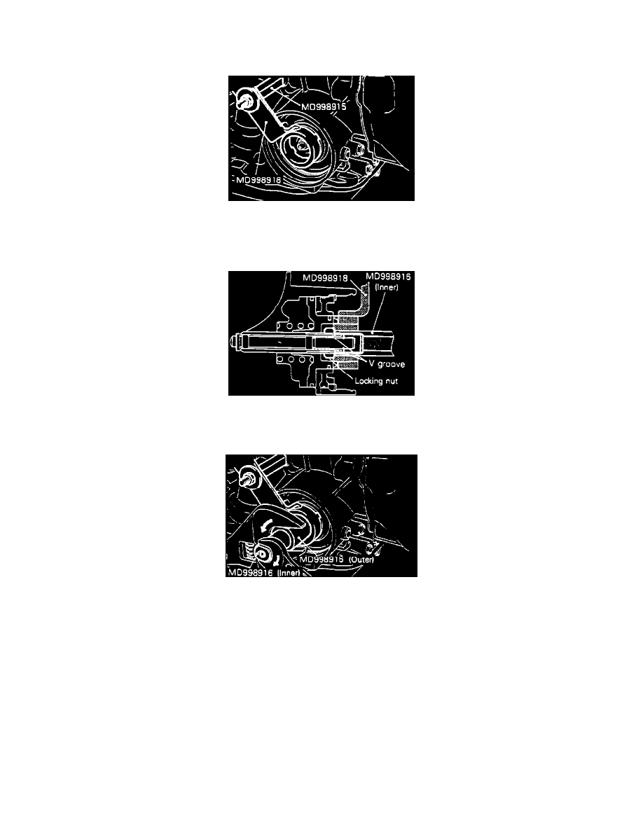
Fig. 8 Installing Holding Fixture
3.
Install holding fixture No. MD998914 and adapter MD998915-A as shown in Fig. 8. Ensure piston is not pushed in by tool. When installing
adapter to brake pressure take-out port, tighten only by hand.
Fig. 9 Loosening Locknut
4.
Loosen locknut past V channel in adjuster rod, then tighten tool No. MD998916 (inner) until there is contact with locknut Fig. 9.
Fig. 10 Using Tool MD998916
5.
Attach tool No. MD998916 (outer) to locknut. Turn outer tool to left and inner tool to right to lock locknut and inner tool, Fig. 10.
6.
Install torque wrench to inner tool. Torque locknut to 7.2 lb-ft, then loosen locknut and retorque to 3.6 lb-ft. Back off inner tool by 2-2 1/2 turns.
7.
Attach outer tool to locknut. Turn outer tool to right and inner tool to left to unlock locknut and inner tool.
8.
Tighten locknut by hand until it contacts piston. Using torque wrench, torque locknut to 18-23 lb-ft.
9.
Remove holding fixture, and install a plug on brake pressure take-out port.