
FE120 L4-4.9L DSL Turbo (2005)
2.1. Exhaust gas recirculation valve
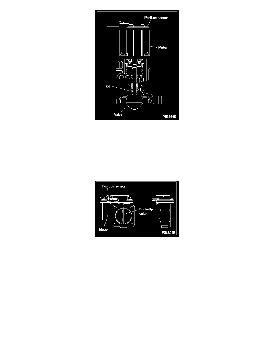
3. Intake throttle control function
-
When the engine electronic control unit determines from sensor data on the engine speed and engine loading that the vacuum pressure in
the intake manifold is low, it increases the amount of exhaust emissions introduced into the intake manifold by determining an appropriate
butterfly valve opening and by sending corresponding control signals (these indicate the target throttle opening) to the throttle electronic
drive unit.
-
The throttle electronic drive unit activates the valve motor. At the same time, it monitors the valve opening using a position sensor and
sends this information (this indicates the actual throttle opening) to the engine electronic control unit.
This operation makes it possible for the target throttle opening indicated by the engine electronic control unit to be precisely maintained.
3.1 Intake throttle
-
In accordance with signals from the throttle electronic drive unit, the motor opens and closes the butterfly valve, thereby adjusting
the intake air amount such that the effectiveness of exhaust gas recirculation is maximized.
4. Fault diagnosis function
-
While the starter switch is in the ON position, the engine electronic control unit continuously monitors the electronic drive units and
sensors for faults. In the event that the engine electronic control unit finds a component faulty, it causes an indication to be made in the
meter cluster to alert the driver. At the same time, it memorizes the fault location in the form of a diagnosis code and starts a control
during fault.
-
While the engine is running, the exhaust gas recirculation electronic drive unit and throttle electronic drive unit continuously monitor
communication with the position sensor and motor of the exhaust gas recirculation valve, communication with the position sensor and
motor of the intake throttle, and communication with the engine electronic control unit. In the event that they identify a fault, they send
fault data to the engine electronic control unit.
-
While control necessitated by a fault is taking place, the system's functionality is limited to ensure vehicle and driver safety. It is possible
to read the memorized diagnosis code using a Multi-Use Tester or from flashing of the warning lamp.
NOTE:
-
Diagnosis codes shown by the Multi-Use Tester and those indicated by flashing of the warning lamp are different.
-
The Multi-Use Tester is capable of showing more detailed diagnosis codes.