
FE120 L4-4.9L DSL Turbo (2005)
Fuel Pressure Sensor/Switch: Description and Operation
Overview
-
In the common rail system, an electronic control unit monitors various aspects of the engine (engine speed, throttle opening, coolant temperature,
etc.) using information from sensors. In accordance with these data, the electronic control unit effects control over the fuel injection quantity, fuel
injection timing, and fuel injection pressure in order to optimize the engine's operation.
-
The electronic control unit has a diagnosis function that enables it to recognize abnormalities in the common rail system's major components and
alert the driver to them.
-
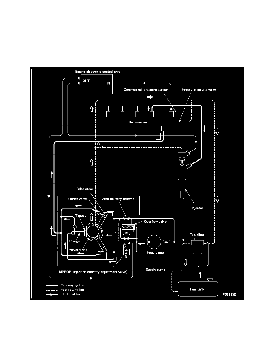
The common rail system consists mainly of an electronically controlled supply pump; injectors; a common rail; and the electronic control unit and
sensors that are used to control the other components.
-
When the engine is cranked by means of the starter switch, the feed pump (this is located inside the supply pump) simultaneously draws fuel from
the fuel tank and feeds it via the fuel filter to the MPROP (injection quantity adjustment valve). A quantity of fuel metered by the MPROP is
supplied via the inlet valves to the plunger chambers.
-
The fuel in the plunger chambers is pressurized. The outlet valves are then opened, and the fuel is fed under pressure to the common rail.
-
The pressurized fuel is held in the common rail and then uniformly fed to the injectors.
-
In response to signals from the engine electronic control unit, a magnetic valve in each injector causes the injector to inject fuel into the relevant
combustion chamber at the optimal timing and in the optimal quantity.