
Galant L4-1997cc 2.0L SOHC 16 Valve (1993)
The pick-up uses two luminous diodes and two photo diodes to detect the two types of slits.
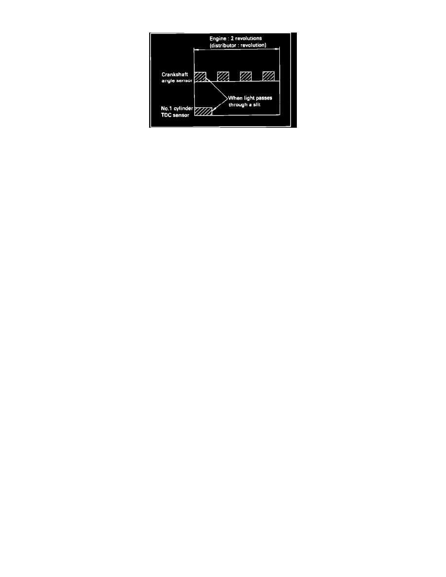
Photoelectric Signal Pattern
Operation
The disc rotates in a narrow gap between the luminous diodes and the photo diodes.
As the distributor shaft rotates, the slits pass between the sets of diodes.
-
The light emitted from the luminous diodes passes through the slits to the photo sensing diodes.
-
When the photo diodes detect light, they become conductive and generate a signal, which is sent to the Control Unit.
The Control Unit bases the sequence of the fuel injector firing on the signal generated when the single inner slit passes between the inner diode
pair.
The slits at the outer circumference of the disc represent the exhaust stroke and detect the position of the crankshaft (and, therefore, the piston)
relative to top dead center.
-
The Control Unit uses this signal to determine the fuel injection pulse width, ignition timing, and the intake air flow rate for each revolution of
the engine.