
Galant L4-1997cc 2.0L SOHC 16 Valve (1993)
ECM Terminal Voltages - 3 of 3
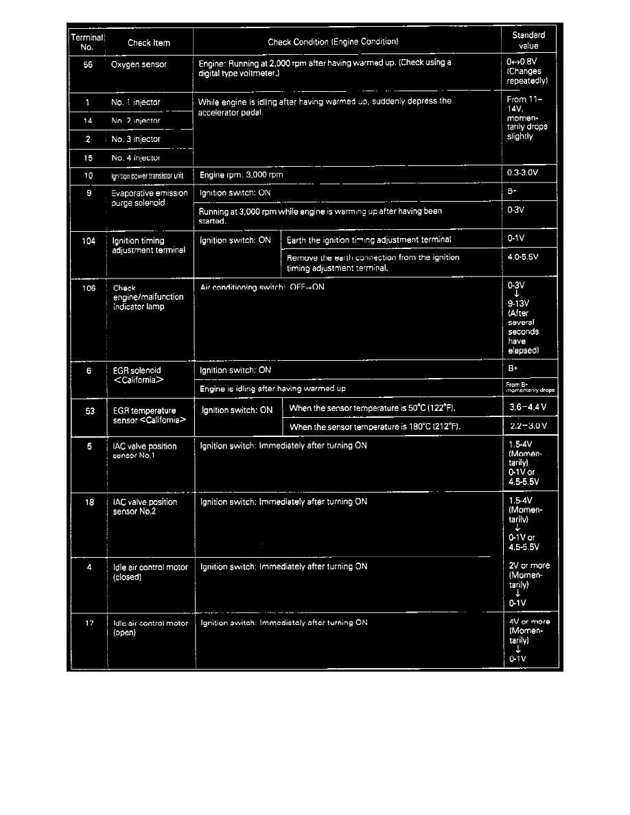
(2) At each terminal of the engine control module connector, insert the extremely fine probe from the wire side, and measure the Voltage referring to
the check chart.
NOTE:
1. In the state in which the connector of the engine control module is connected, measure the Voltage.
2. Measure the Voltage across each terminal to the terminal No. 26. (ground terminal).
3. You may find it convenient to pull out the engine control module to make it easier to reach the connector terminals.