
Galant L4-1997cc 2.0L SOHC 16 Valve (1993)
COMPONENT TEST
1. Remove the control relay.
2. Using an Ohm meter, check the resistance between the terminals as shown in FIG. 1.
Fig. 2 Control Relay Test
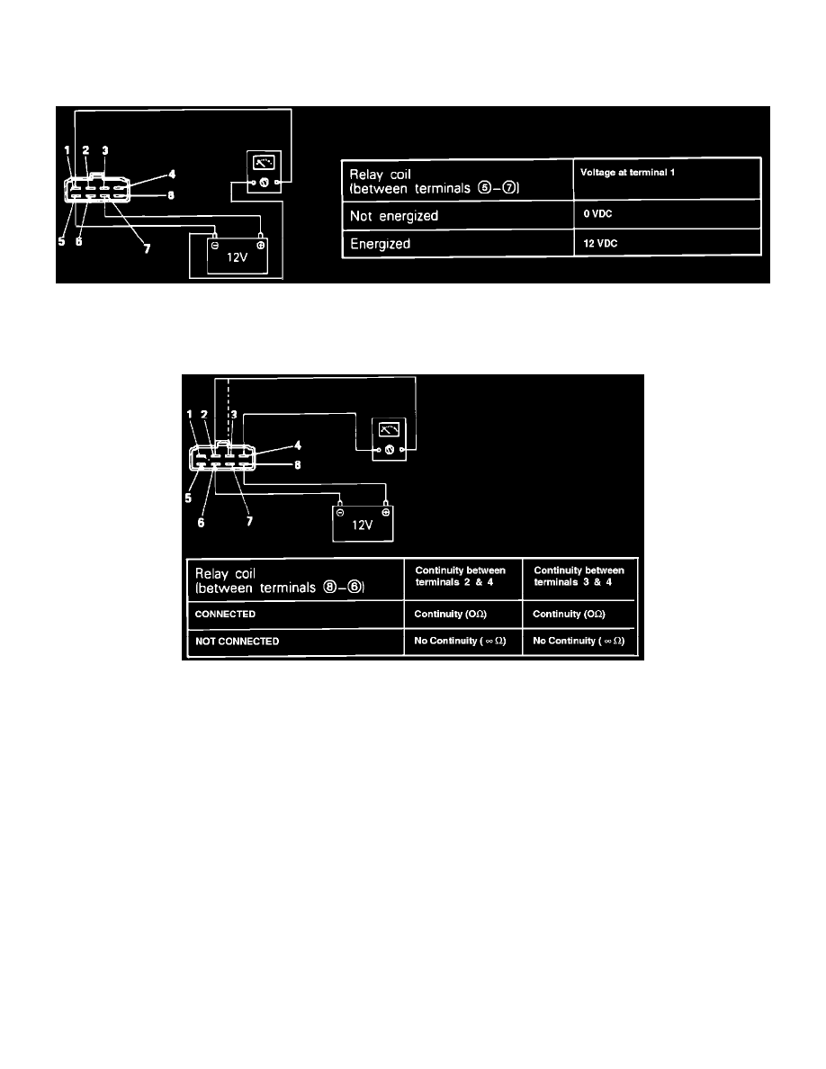
3. Using an Ohm meter, check the resistance terminals 1 and 4, when Voltage is supplied and not supplied between terminals 6 and 7 as shown in
FIG. 2.
Fig. 3 Control Relay Test
4. Using an Ohm meter, check the resistance terminals 2 and 4, when Voltage is supplied and not supplied between terminals 6 and 8 as shown in
FIG. 3.
HARNESS TEST
1. Disconnect the control relay and turn the key to the ON position.
2. Using a Volt meter, check the Voltage between relay harness terminal 8 and ground.
Voltage: ............................................................................................................................................................................................ System Voltage
3. Turn the key to the OFF position.
4. Using an Ohm meter, check for continuity between relay harness terminal 6 and ground.
Continuity: ............................................................................................................................................................................................ Should exist
5. Using a Volt meter, check the Voltage between relay harness terminal 4 and ground.
Voltage: ............................................................................................................................................................................................ System Voltage
6. Disconnect the negative battery cable and the ECU connector.
7. Using an Ohm meter check for continuity between relay harness connector 3 and ECU harness connectors 12 and 25.