
Galant L4-1997cc 2.0L SOHC 16 Valve (1993)
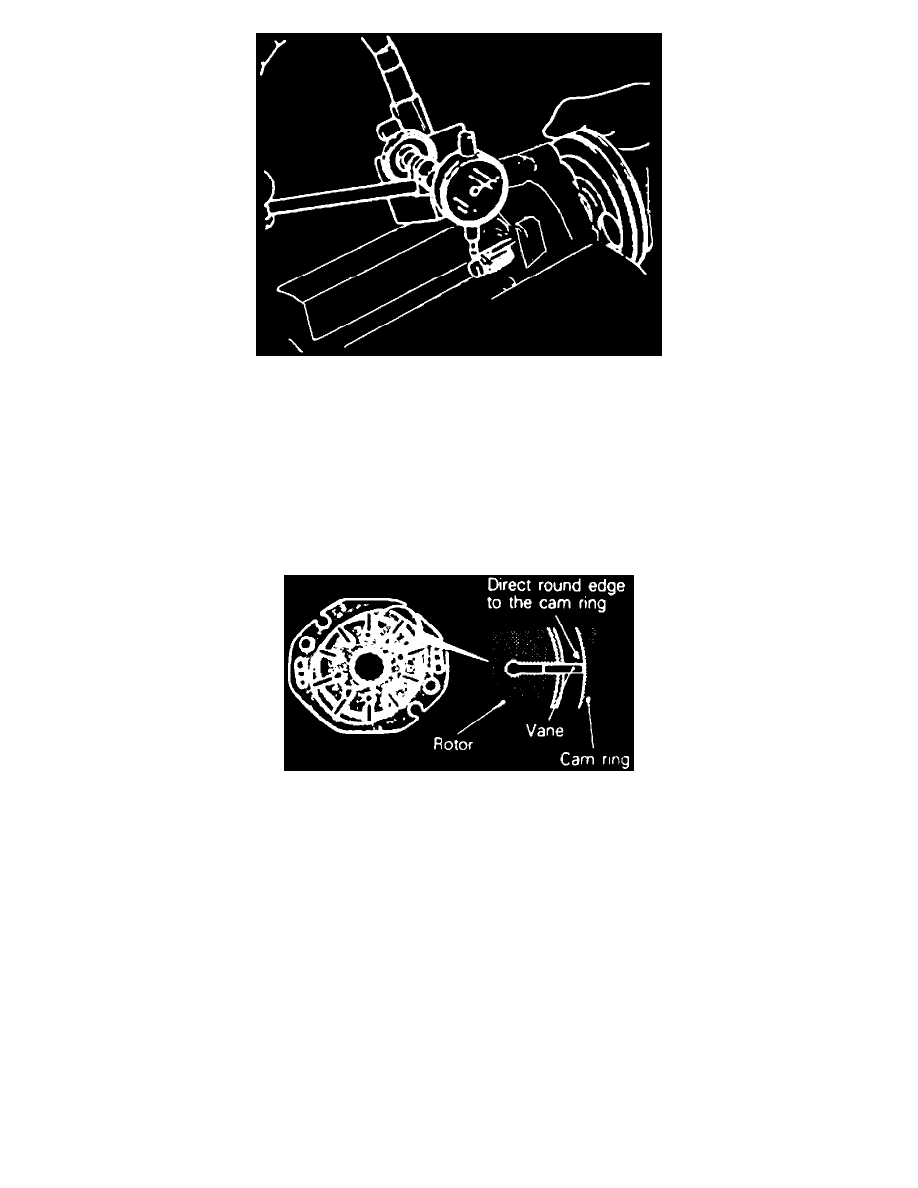
Fig. 37 Pump Backlash Measurement
8. Place a dial indicator at end of pulley shaft, Fig. 37.
9. Move pulley assembly up and down and measure freeplay. Freeplay should not exceed 0.004 inch.
10. Reverse numbered sequence shown in Fig. 35 to assemble power steering pump, noting the following:
a. Install spring in oil pump body with larger diameter end at terminal assembly side.
b. Apply Dexron II or Diamond ATF SP ATF fluid to O-rings, flow control valve, cam vanes & cam ring.
c. Align dowel pin of pump body with dowel pin hole of side plate to install side plate.
d. Install rotor to pulley assembly with rotor punch mark at pump cover side.
e. Install rotor snap ring and ensure snap ring is properly countersunk.
f.
Align dowel pin cutouts in side plate with dowel pin holes of cam ring then install cam ring with punch mark toward pump body side.
Fig. 38 Rotor Vane Orientation
g. Install vanes on rotor as shown in Fig. 38.