
Galant L4-1997cc 2.0L SOHC 16 Valve (1993)
Axle Shaft Assembly: Removal and Replacement
Front Wheel Drive
1.
Remove dust cover, cotter pin and driveshaft nut.
2.
Raise and support vehicle.
3.
Drain transmission oil.
4.
Disconnect lower arm ball joint from knuckle, then remove stabilizer and strut bars from lower arm.
5.
On models with driveshaft center bearing, remove bearing bracket attaching bolts.
6.
Insert suitable pry bar between transmission case and driveshaft, then pry driveshaft from transmission. Do not pull on driveshaft and do not
insert pry bar deep enough to damage oil seal.
7.
Using tool No. MB990241 or equivalent, remove driveshaft from hub.
8.
Reverse procedure to install, noting the following:
a. Ensure driveshaft washer is correctly installed.
b. Lower vehicle to ground, then attach and adjust driveshaft nut, torquing to 144-188 ft. lbs.
c. If cotter pin holes do not line up, tighten bolt without exceeding torque of 188 ft. lbs., until holes line up.
d. Install cotter pin. Always use new cotter pins.
e. Refill transaxle to proper level.
All Wheel Drive
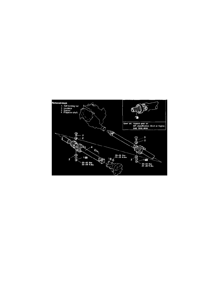
REPLACE
Fig. 3 Driveshaft Replacement
1.
Remove spacers, Fig. 3. Number of spacers differ on each vehicle, note for reference during installation.
2.
Mark mating marks on differential companion flange and flange yoke, then remove propeller shaft. Remove propeller shaft in a straight and
level manner to ensure boot is not damaged through pinching.
3.
During removal do not lower rear end of vehicle or oil will flow out of transfer case. Avoid damage to oil seal lip of transfer case and
entry of foreign materials.
4.
Inspect propeller shaft, sleeve, center and flange yokes for wear, damage or cracks and replace as necessary.
5.
Inspect propeller shaft for bends, twisting or damage and replace as necessary.
6.
Measure propeller shaft runout with a dial indicator. Runout should be 0.024 inch or less.
7.
Inspect universal joints and center bearing for damage, deterioration and smooth operation.
8.
Reverse procedure to install, noting the following:
a. Install spacers and insulators. When installing center bearing, assemble same spacers as removed or new spacers of equal thickness.