
Galant L4-2.0L SOHC (1989)
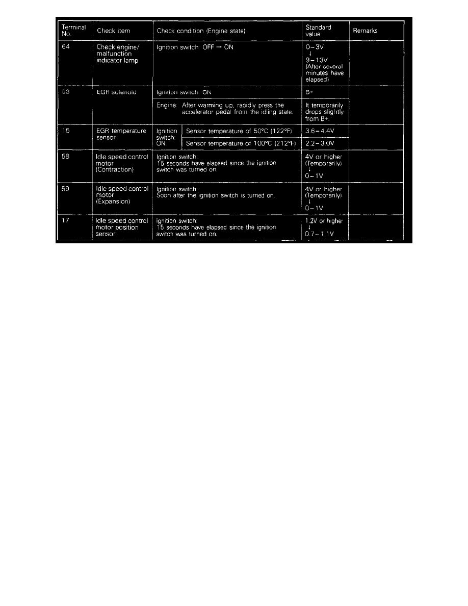
(2) At each terminal of the engine control module connector, insert the extremely fine probe from the wire side, and measure the voltage referring to
the check chart.
NOTE:
1. In the state in which the connector of the engine control module is connected, measure the voltage.
2. Measure the voltage across each terminal to the terminal No. 106. (ground terminal).
3. You may find it convenient to pull out the engine control module to make it easier to reach the connector terminals.
4. Inspection need not be executed in the chart's sequence.
Caution: Short-circuiting the positive (+) probe between a connector terminal and ground could damage the vehicle wiring, the sensor, the engine
control module, or all three. Use care to prevent this!
(3) If voltmeter shows any deviation from standard value, check the corresponding sensor, actuator and related electrical wiring, then repair or
replace.
(4) After repair or replacement, recheck with the voltmeter to confirm that the repair has corrected the problem.