
Galant L4-2.0L SOHC (1989)
Assembly
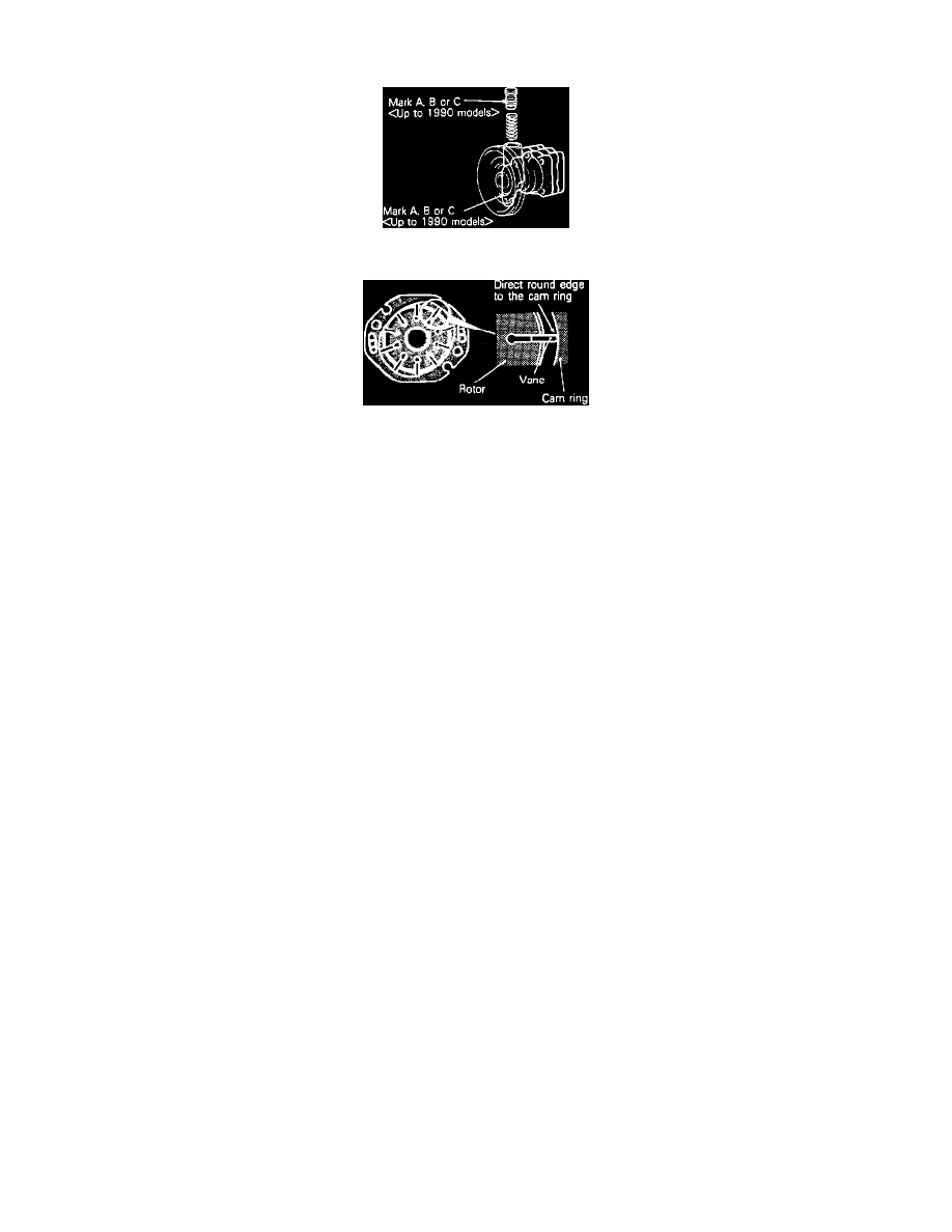
Fig. 26 Flow Control Valve Identification Mark
Fig. 7 Rotor Vane Installation Direction
Assemble power steering pump in reverse numbered sequence shown in Figs. 23 and 24, noting the following:
1.
Install spring in oil pump body with larger diameter end at terminal assembly side.
2.
Apply Dexron II ATF fluid to O-rings, flow control valve, cam vans & cam ring.
3.
On 1989-90 models, if the flow control valve is to be replaced, use valve with corresponding letter on oil pump body, Fig. 26.
4.
On all models, align dowel pin of pump body with dowel pin hole of side plate to install side plate.
5.
Install rotor to pulley assembly with rotors's punch mark is at pump cover side.
6.
Install rotor snap ring and ensure snap ring is properly countersunk.
7.
On 1989-90 models, align dowel pins of pump body with dowel pin holes of cam ring then install cam ring with punch mark toward pump body
side.
8.
On 1991-92 models, align dowel pin cutouts in side plate with dowel pin holes of cam ring then install cam ring with punch mark toward pump
body side.
9.
On all models, install vanes on rotor as shown in Fig. 7.