
Galant V6-3.0L SOHC (2003)
TECHNICAL DESCRIPTION (COMMENT)
The power supply circuit to the column switch (column-ECU) may be defective. If the battery power supply circuit (terminal 1 of the column switch) to
the ECU is damaged also check the power supply circuit from the ignition switch (IG1) (terminal 9 of the column switch) and repair if necessary.
TROUBLESHOOTING HINTS
-
The ETACS-ECU may be defective
-
The column switch may be defective
-
The wiring harness or connectors may have loose corroded or damaged terminals or terminals pushed back in the connector
DIAGNOSIS
Required Special Tools:
-
MB991223: Harness Set
-
MB991502: Scan Tool (MUT-II)
-
MB991862: SWS monitor kit
STEP 1. Use scan tool MB991502 to select "ECU COMM CHK" on the SWS monitor display.
Check the following ECUs:
-
ETACS-ECU
-
Column-ECU
CAUTION:
To prevent damage to scan tool MB991502, always turn the ignition switch to the "LOCK" (OFF) position before connecting or disconnecting scan tool
MB991502. Connect the DLC harness before connecting the column-ECU harness. Be sure to connect SWS monitor kit MB991862 after turning on scan
tool MB991502.
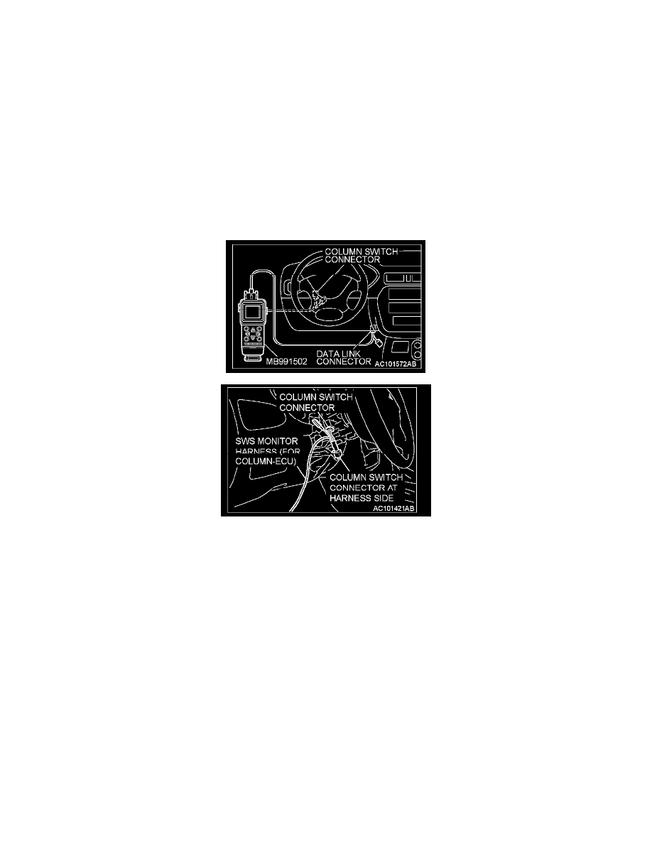
1. Connect scan tool MB991502 to the data link connector.
2. Connect SWS monitor kit MB991862 to the column switch connector.
3. Turn the ignition switch to the "ON" position.
4. Operate scan tool MB991502 according to the procedure below to display "ECU COMM CHK."
1. Select "SYSTEM SELECT"
2. Select "SWS."
3. Select "SWS MONITOR."
4. Select "ECU COMM CHK."
5. Scan tool MB991502 should show "OK' on the "ECU COMM CHK' menus for both the "ETACS ECU" and the "COLUMN ECU" menus.