
Galant LS V6-3.0L SOHC (1999)
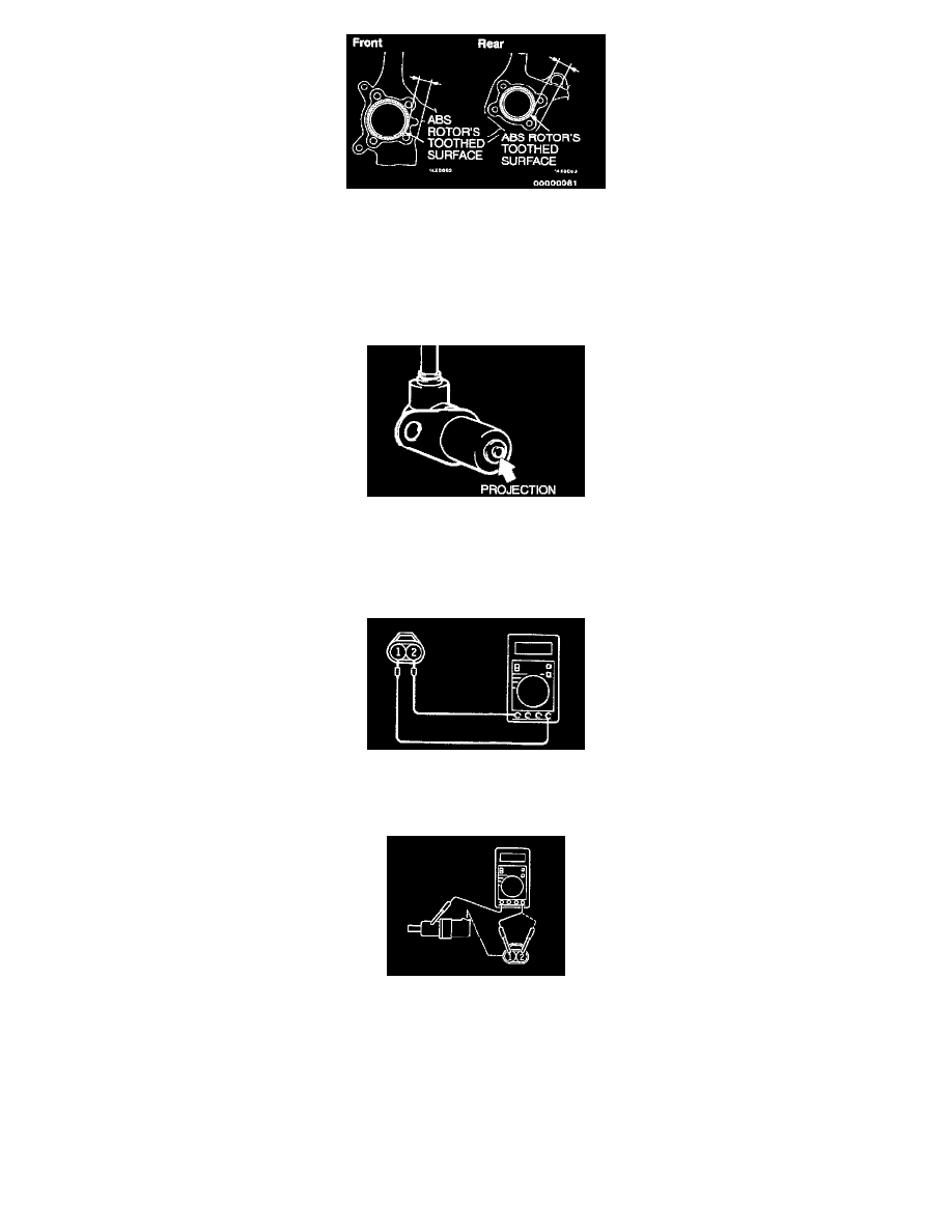
The clearance between the wheel speed sensor and the ABS rotor's toothed surface is not adjustable, but measure the distance between the sensor
installation surface and the ABS rotor's toothed surface.
Standard value: 28.2-28.5 mm (1.10-1.22 inch)
INSPECTION
Speed Sensor Check
1. Check whether any metallic foreign material has adhered to the projection at the speed sensor tip. Remove any foreign material.
Also check whether the pole piece is damaged. Replace it with a new one if it is damaged.
NOTE: The projection can become magnetized due to the magnet inside the speed sensor, causing foreign material to easily adhere to it. The
projection may not be able to correctly sense the wheel rotation speed if foreign matter is on it or if it is damaged.
2. Measure the resistance between the speed sensor terminals.
Standard value: 1.28-1.92 k ohms
If the internal resistance of the speed sensor is not within the standard value, replace it with a new speed sensor.
3. Remove all connections from the speed sensor, and then measure the resistance between terminals (1) and (2) and the body of the speed sensor.
Standard value: 100 k ohms or more
If the speed sensor insulation resistance is not within the standard value range, replace with a new speed sensor.
4. Check the speed sensor cable for breakage, damage or disconnection. Replace with a new one if a problem is found.
NOTE: When checking for cable damage, remove the cable clamp part from the body and then gently bend and pull the cable near the clamp.
Toothed ABS Rotor Check