
Galant LS V6-3.0L SOHC (1999)
DIAGNOSIS
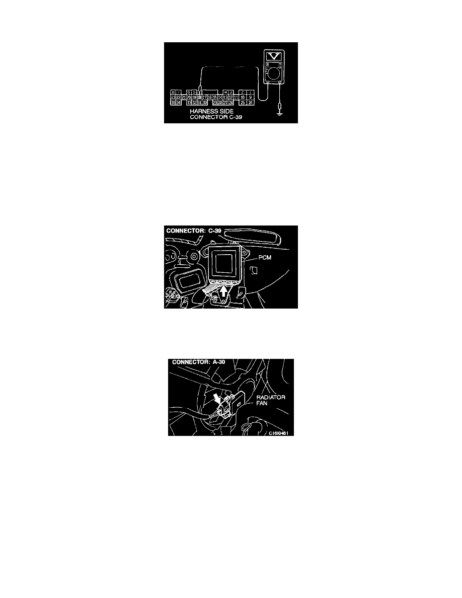
STEP 1.
Measure the voltage at the PCM connector C-39.
1. Disconnect the connector C-39 and measure the harness side.
2. Turn the ignition switch "ON."
3. Measure the voltage between the terminal 18 and ground.
-
Voltage should be between 4.8 and 5.2 volts. (Fan rotates at high speed.)
4. Connect a jumper cable between 18 and ground.
-
Fan stops.
5. Turn the ignition switch "OFF."
If within specifications, go to Step 2.
If not within specifications, go to Step 3.
STEP 2.
Check the harness connector C-39 at the PCM for damage.
If harness connector C-39 is not damaged, replace the PCM.
If the harness connector C-39 is damaged, repair or replace them. Refer to Harness Connector Inspection >. Then check the malfunction is
eliminated.
STEP 3.
Check the harness wire between the fan controller connector A-30 and the PCM connector C-39.
NOTE: Check the wire after checking the intermediate connector C-04. If the intermediate connector C-04 is damaged, repair or replace
it. Refer to Harness Connector Inspection >. Then check that the malfunction is eliminated.
If the wire between the fan controller connector A-30 and PCM connector C-39 is damaged, repair it.
If the wire between the fan controller connector A-30 and PCM connector C-39 is not damaged, check the radiator fan and A/C compressor
fan circuit. Refer to Diagnosis.
Then check the malfunction is eliminated.