
Galant LS V6-3.0L SOHC (1999)
-
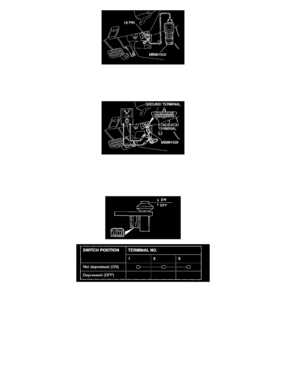
Using scan tool MB991502
1. Connect Scan Tool MB991502 to the data link connector.
2. Check that the tone alarm of the scan tool sounds when the driver's door is opened.
If the tone alarm of the scan tool does not sound, the input signal from the driver's door switch is not normal. Go to Step 2.
If input signal normal, go to Step 6.
-
Using a voltmeter
1. Use special tool MB991529 to connect a voltmeter between ground terminal 4 or 5 and ETACS-ECU terminal 9 of the data link connector.
2. If a voltmeter indicator deflects once when the driver's door is opened, the ETACS-ECU input signal for the driver's door switch circuit system
is normal.
If the input signal of the driver's door switch is not normal, go to Step 2.
If the input signal is normal, go to Step 6.
STEP 2. Check the driver's door switch for continuity.
1. Remove the driver's door switch.
2. Check for continuity at the driver's side door switch.
If there is continuity, go to Step 3.
If there is no continuity, replace the switch. Then check that the malfunction is eliminated.