
Galant LS V6-3.0L SOHC (1999)
Simplified Wiring System: Symptom Related Diagnostic Procedures
Input Signal Check
Input Signal Check Function
This mode checks the switch input signals to each ECU incorporated in the SWS.
If a defect is found at this check, carry out the troubleshooting by referring to Symptom Chart.
<When using scan tool MB991502>
Required Special Tool:
MB991502: Scan Tool (MUT-II)
CAUTION: To prevent damage to scan tool MB991502, always turn the ignition switch to "LOCK" (OFF) position before connecting or disconnecting
scan tool MB991502.
1. Connect scan tool MB991502 to the data link connector.
2. If input signal is sent to the data link connector, tone alarm of scan tool MB991502 will sound.
3. Turn the ignition switch to "LOCK" (OFF) position.
4. Disconnect scan tool MB991502.
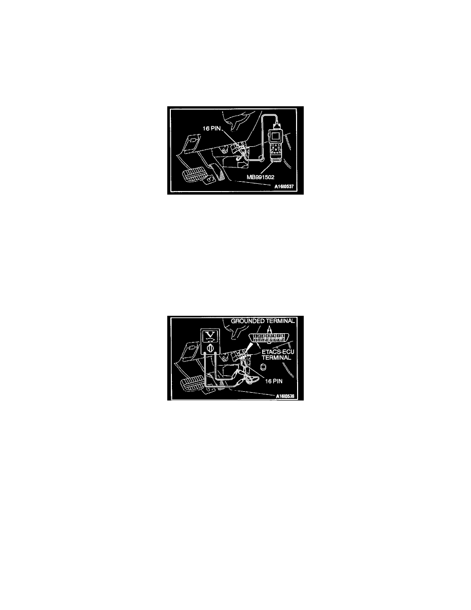
<When using a voltmeter>
Required Special Tool
MB991529: Diagnostic Trouble Code Check Harness
1. Connect special tool MB991529 to connect a voltmeter between grounded terminal 4 or 5 and ETACS-ECU terminal 9 of the 16 pin data link
connector.
2. If input signal is sent to the data link connector, the voltmeter needle will fluctuate once.
3. Disconnect special tool MB991529.